Master control section – Yamaha MC1602 User Manual
Page 7
Attention! The text in this document has been recognized automatically. To view the original document, you can use the "Original mode".
[
Master Control Section
<0
7 ? . ? J 0
-A
\ VU
AUX/CUE
7 5 3 OPEAK
10 I
20
-A
\ VU
L ST R
10 7 , f . ■ ^ 1 OPEAK
' \ VU ^
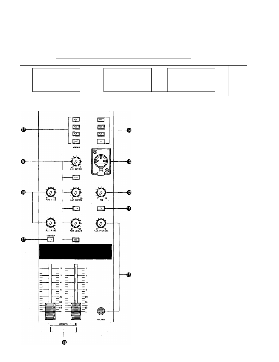
0 AUX SEND (1,2 & 3) Controls & CUE Switches
These adjust the overall output level of the auxiliary
"mixes" set up using the AUX 1, AUX 2 and AUX 3 con
trols on the input channels. AUX SEND 1 sets the overall
level of the AUX 1 mix signal appearing at the AUX
SEND 1 jack, AUX SEND 2 sets the overall level of the
AUX 2 mix signal appearing at the AUX SEND 2 jack,
and AUX SEND 3 sets the overall level of the AUX 3
mix appearing at the AUX SEND 3 jack. These controls
should be used to optimally match the AUX SEND out
put level of the mixing console to the input sensitivity of
the effect unit, signal processing device or amplifier used.
The CUE switches associated with each AUX SEND con
trol can be used to send the corresponding AUX SEND
signal to the PHONES jack via the CUE/PHONES level
control. The AUX cue signal will be added to any other
active cue signal. If you want to monitor only the signal
from a single AUX buss, make sure all other CUE switches
are turned OFF.
D AUX RTN 1 & AUX RTN 2 Controls
These controls adjust the level of the signal received at the
rear-panel AUX RTN jacks and mixed into the main
stereo program. Since stereo AUX returns are provided
(AUX RTN 1 L & R, AUX RTN 2 L & R) the AUX RE
TURN controls simultaneously adjust the level of the
signals appearing at the corresponding L and R return
inputs. The returned L and R channel signals are sent to
the L and R stereo buss lines. If only a single-channel
signal is returned (i.e. a plug is inserted into only the L or
R return jack), the signal will be fed to both the L and R
channels of the stereo buss.