Limiter indicator, Protection indicator, Line and mic input connectors – Yamaha EM1620 User Manual
Page 6: Phantom master switch, Sp out 1 and 2 jacks, Rear panel
Attention! The text in this document has been recognized automatically. To view the original document, you can use the "Original mode".
® LIMITER indicator
EMI620 is equipped with a limiter circuit which can
limit the maximum level of signal at the SP OUT to
prevent the signal from distorting.
The LIMITER indicator is lit when the limiter cirT
cuit is activated.
© PROTECTION indicator
The PROTECTION indicator lights for approxi
mately 6 seconds after the POWER switch is pressed
to indicate that the protection circuitry is operating.
No sound is output at the SP OUT while this indica
tor is lit. This indicator will also light and the sound
will be cut off at the SP OUT when the protection
circuitry is activated at any other time during the
amplifier operation due to factors such as a detec
tion of excessive DC voltage at the SP OUT or a
thermal overload. When the problem is corrected,
the protection circuitry is automatically deactivated,
the indicator goes out, and the amplifier resumes
normal operation.
REAR PANEL
MAXRMS.<
200W/4P (
CLASS 2 w ms
MAY 0---------
POWERED MIXEH
MODEL EM1820
120V 180W SOHl'V
YAMAHA CDRPO(WX)N
MADE IN nuWAN ЕПв1
sen NO. L.^
Ф
r
MON OUT +4dS
e
r
UNE OUT +4dB -Ч
e
UtUnED
SERVICEABie
REFER SERVICINO TO
semncE PER30(«e.
WARNING TO REixlx
tme
risk
OF FIRE on Е1ЕСШС ----------------
00 NOT BtPOX
this
TO RAH OR MOISnjn
é
Cooling Fan
(Air intake)
r
EFF SEND -10dB -ч
r EFF RTN -20dB -ч
2 1
r
REG OUT -10dB -Ч
2 1
r
TAPE IN -lOdB -Ч
2 1
Ш
ШШ
©®© ©®©
# Ф
® Щ
<3)
UL/eSA model
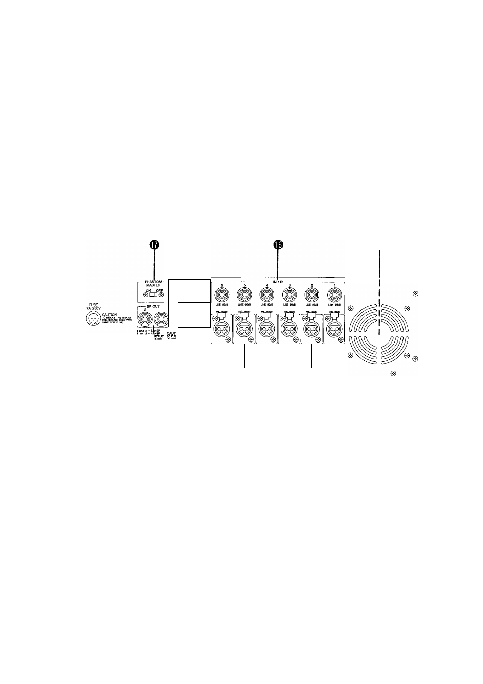
© LINE and MIC INPUT connectors
Each input channel offers a choice of two input
connectors: a MIC IN connector, a balanced 4 kohm
impedance XLR-3-31 connector; and a LINE IN
connector, an unbalanced 10 kohm impedance 1/4"
phone jack. The MIC connectors are primarily in
tended for use with professional low-impedance
microphones or electronic instruments having low-
impedance balanced outputs. The LINE connectors
will accept unbalanced signals from musical instru
ments or other such source equipment.
© PHANTOM MASTER switch
This switch applies built-in standard +48 V power
to all MIC (XLR) input connectors for biasing Phan
tom powered condenser microphones.
MICROPHONE CABLES AND MICROPHONES
CONNECTION
TO PREVENT HAZARD OR DAMAGE, ENSURE
THAT ONLY MICROPHONE CABLES. AND
MICROPHONES DESIGNED TO THE IEC268-
15A STANDARD ARE CONNECTED.
© SP OUT 1 and 2 jacks
SP OUT I and SP OUT 2 are standard mono 1/4"
phone jacks. The jacks are wired in parallel and, as a
result, if you connect a speaker system to only one
of the two jacks, then the total load impedance of
the speaker system may be no less than 4 ohms. If
you plug speaker systems into both of the SP OUT
jacks, the total load impedance of each speaker sys
tem must be no less than 8 ohms.