Operation, Maintenance, Wiring diagrams – Chromalox ADH-005 User Manual
Page 4
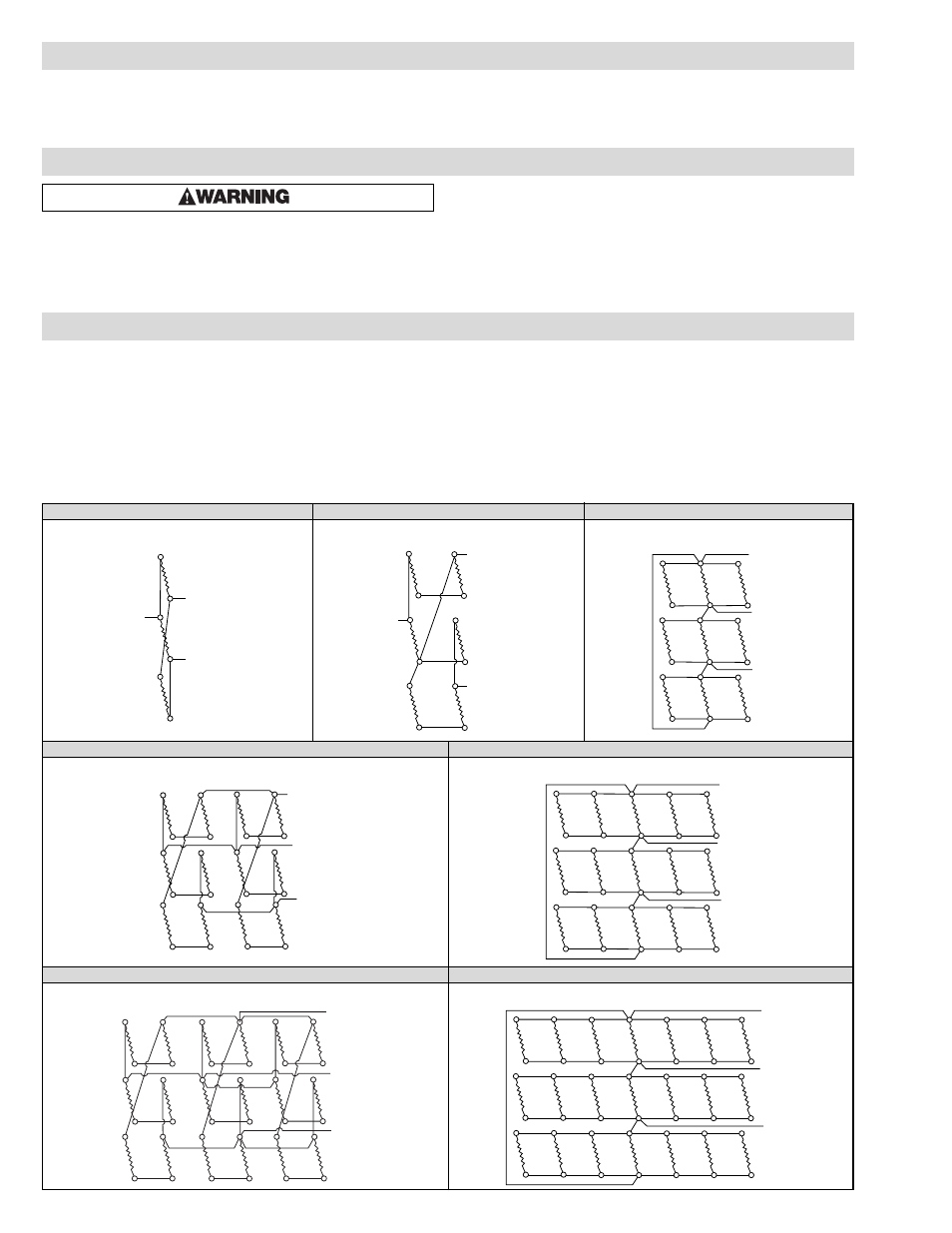
ADH-005, ADHT-005
ADH-010, ADHT-010
ADH-015, ADHT-015
ADH-020, ADHT-020
ADH-025, ADHT-025
ADH-030, ADHT-030
ADH-035, ADHT-035
Do not operate heater at voltages in excess of that stamped on
the heater since excess voltage will shorten heater life.
OPERATION
ELECTRIC SHOCK HAZARD. Disconnect all power
before installing or servicing heater. Failure to do
so could result in personal injury or property dam-
age. Heater must be installed by a qualified person
in accordance with the National Electrical Code,
NFPA 70.
1. Periodically clean terminals and terminal covers of dust and corro-
sion to maintain good electrical connections and to permit rapid
heat dissipation. Use airblast, and be careful to avoid damage to
mica insulation.
2. Check for loose terminal connections. Tighten as necessary.
MAINTENANCE
ADH-005, ADHT-005, ADH-010, ADHT-010,
ADH-015, ADHT-015, ADH-020, ADHT-020,
ADH-025, ADHT-025, ADH-030, ADHT-030,
ADH-035, ADHT-035 . . . . . . . . . . . . . . . . . . . . . . . . . . . . . . . .4
ADH-040, ADHT-040, ADH-045, ADHT-045,
ADH-050, ADHT-050, ADH-060, ADHT-060,
ADH-080, ADHT-080, ADH-090, ADHT-090,
ADH-100, ADHT-100 . . . . . . . . . . . . . . . . . . . . . . . . . . . . . . . .5
ADHT-120, ADH-144, ADHT-160, ADH-162,
ADHT-180, ADH-216F, ADHT-240F, ADH-270F,
ADH-300F . . . . . . . . . . . . . . . . . . . . . . . . . . . . . . . . . . . . . . . .6
WIRING DIAGRAMS
1 Circuit, 3 Elements per Heater
1 Circuit, 6 Elements per Heater
1 Circuit, 9 Elements per Heater
AL1
AL2
AL3
AL1
AL3
AL2
AL1
AL2
AL3
1 Circuit, 12 Elements per Heater
1 Circuit, 15 Elements per Heater
AL1
AL2
AL3
AL1
AL2
AL3
1 Circuit, 18 Elements per Heater
1 Circuit, 21 Elements per Heater
AL1
AL2
AL3
AL1
AL2
AL3
Circuit A
Circuit A
Circuit A
Circuit A
Circuit A
Circuit A
Circuit A
4