Installation guide, Anti-theft system – Panasonic CQ-DFX777EW User Manual
Page 7
Attention! The text in this document has been recognized automatically. To view the original document, you can use the "Original mode".
|CQ-DFX777EW|
Installation Guide
(continued)
O
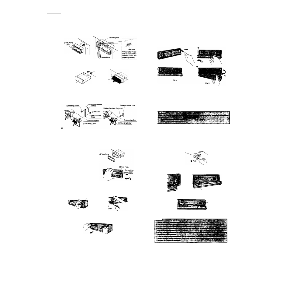
Installation Procedures
Hota: Dlaconnact th« ubi* from tlia negatlva (-) binary Mrmfnal.
1. Secure Mounting Collar
InSBrt Mourting Collar (5 irto tt» dashboard, and bend the mounting tabs out with a screwdtiver.
Dashboard
2. Secure the rear of the unit.
a) ChscK the electrical connectiohs by refernng to thia ogarating instructions. (• Page 32)
b) Connect Mounting Boit t^. using a suitable wrancti,
cj Insert Power Connector ® to the unit.
d) insort tha unit into the Mounting Collar 0 and push it in until a ''ctick" is heard-
® Power Connector
Unit
® Mounting Bolt
a) Secure the rear of the unit to the car by one of the two recommended methods.
■ Using Rear Support Strap d)
Affl)! one end of Rear Supcod Strap @ to the rear of Ihe unit, and Iha other end to the tire wall of the
car, or soma other metallic area.
■ Using the Rubtwr Cushion (Optional)
(It there is an ensling Rear Support Bracket on the tire wall of the car.)
Cover the Mounting 6oll
Ф
on the rear of the unit with the Rubber Cushion (Optranal), and mount it
into the eMsting Rear Support Bracket.
Fire well of the car
Rear Support Bracket
Installation Guide
(continued)
Anti-Theft System
This unit ts equipped with a removable lace plate. By removing this laca plate, the radio becomes lo-
tally inoperabie. The aecunty indicator will biink.
To Remove the Removable Face Plate
® Switch off ths powsr.
@ Press [OPEN], The rerrxrvable lacs plate wiH be opened. (- Rg. 4)
iJiPush the lace plate to either the right or left, then puU it out toward you. (» Rg. 5)
Security Indicator
The security indicator (* Fig. 7) blinks when the removable face plate is removed from the unit.
To Deactivate the Security Indicator
Pross and hold {9EL] for mora than 2 seconds whan tha power is on, 1_ED OFF" is diaplayad, and
(he security indicator turns oft.
Display
Security indicator
LED ON
Blinks
J
f
Press and hoW [SEL] for more ihan
2
seconds.)
LED OFF
OFF
3r Install Trim Plate
®.
4e After instalfatlong reconnect the
negative <—) battery terminal.
Tc Rempve tha Unit
a) Remove the removabie lace plate.
(• Pago 30.)
b) Rerrxive Trim Plate (j$ with a screwdriver as
shown in the figure.
c) Puli out the unit while pushing the two lock Jevers using the screwdriver. Fig.i. 2)
d) Remove the unit by puiling Jt with both hands. Fig.3)
Fig. 2
Fig. 3
0 As shown in Fig. 6, geniiy push the iower side of the case and open its cover. Keep tha removable
face plate in the case. Then you can salefy take the plate with you.
0 Rernovabte lace piate case OOpen
To Install the Removable Face Plate
0 Fit either the edge of the right or iett hda in the face plate over ihe main unit's pms. and fit it over
on the other side while pushing it.
Fig. 7
Secuitty Indicator
® Aftor tining tfie face plata hblaa, tíy rnoving tha laca plata up and down a taw tímea to maka sure
that It has been finad seouraiy.
Fig.
a
® Close the frant panel and press tha right skis of the taca Plata until a'dicK' Is heard.
rTTw™™