Panel location and mounting, Option 1: no mounting bracket, Panel location and mounting -12 – Dynon Avionics EFIS-D10A Installation Guide User Manual
Page 24
Instrument Installation
Panel Location and Mounting
3-12
EFIS-D10A
Installation
Guide
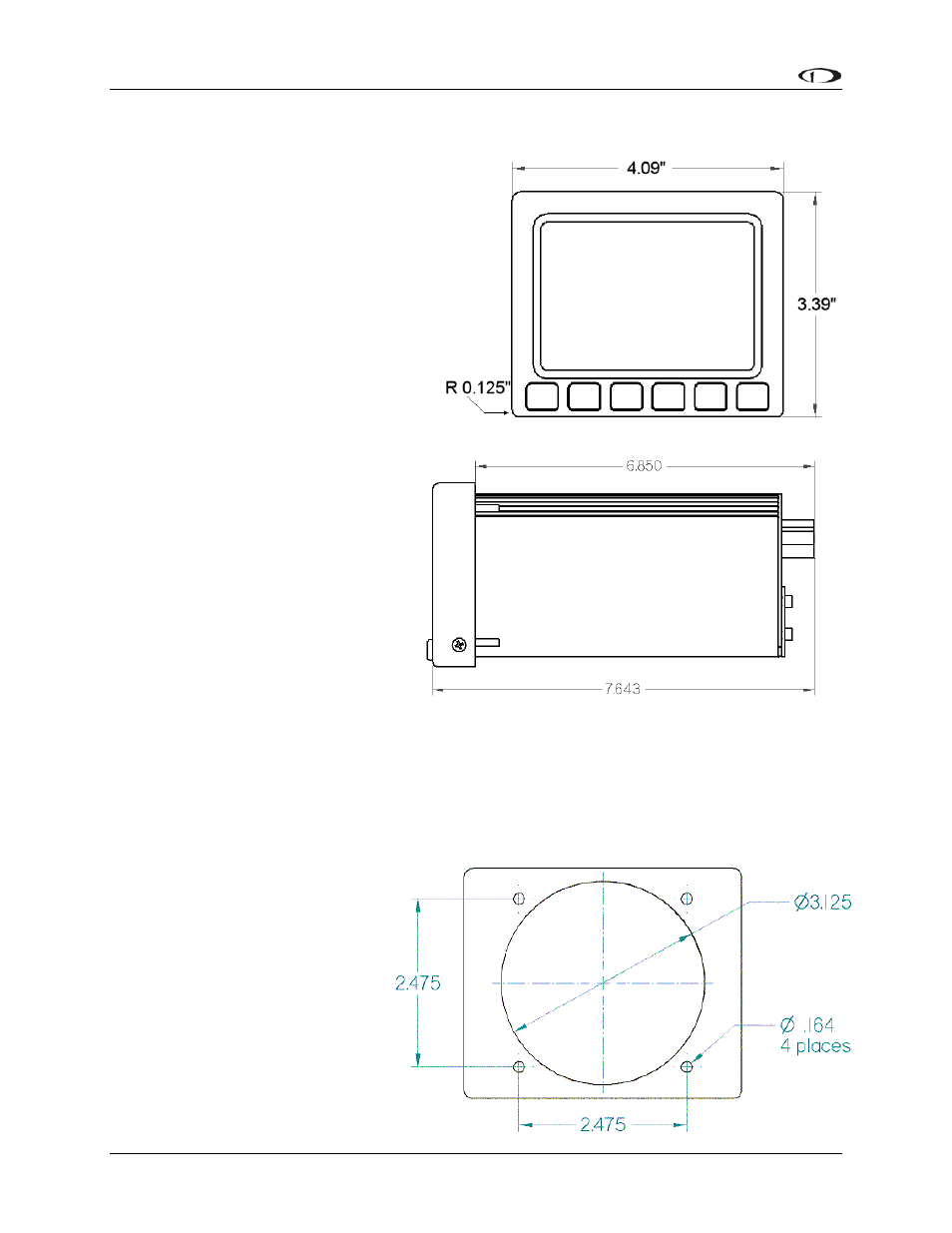
The diagram at right shows the outside
dimensions of the front bezel of the EFIS-
D10A. Note that the instrument is about
seven inches deep and the supplied
harness extends three inches more. Use
the dimensions (in inches) found on the
diagram to plan for the space required by
the instrument. Take the following
considerations into account when s
a mounting location for the EFIS-D10
Avoid placing
electing
A.
the instrument near heater
d
arallel
stm
ns for mounting the EFIS-D10A into your panel: standard or flush. You may
OPTION 1: NO MOUNTING
U
e
tly
vents or any source of extremely hot or
cold air. Keep in mind that the air
surrounding the EFIS-D10A during
operation may be no warmer than 50
C to ensure accurate operation. Plan a
panel location that allows convenient
viewing of the instrument with no
obstruction. When flying straight an
level, the panel angle from vertical
may not be greater than +/- 30
degrees. The unit must also be p
to the roll axis of the aircraft (although
not necessarily located along it), and
have no significant roll angle in the
panel. The firmware supports an adju
roll. Correct attitude performance depends on mounting the EFIS-D10A square with the
direction of flight.
You have two optio
ent for panel tilt, but not for mounting errors in yaw or
use the optional flush-mount bracket, allowing the face of the EFIS-D10A to be flush with your
panel. If you opted to receive the
flush mount bracket, please skip to
Option 2 below. If you opted not
to receive this bracket and wish to
perform the standard install,
follow the options in Option 1
below.
BRACKET
sing this option, you will b
mounting the EFIS-D10A direc
into your panel. The front bezel of