6 starting up and shutting down the device – DVR systems DVR-HDE-960H-960H2 Series User Manual
Page 20
5
7
12
131111
14
1
2
3
4
6
8
9
10
11
15
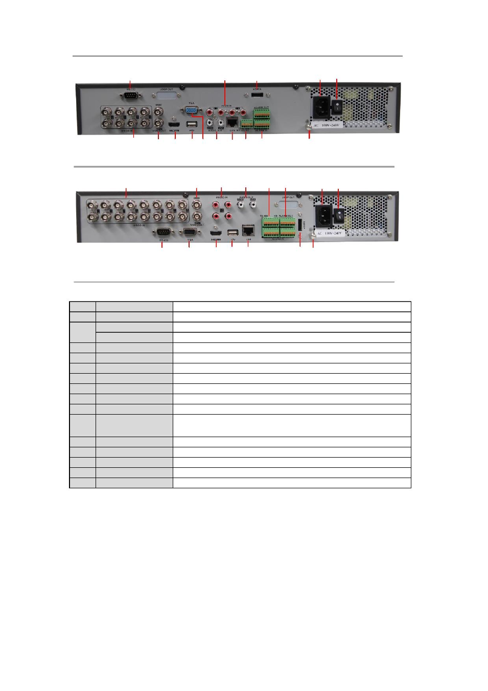
Figure 1. 7 Rear Panel
– 8 Channel
1
2
7
8
10
11
13
14
5
6
3
4
9
12 15
No.
1
2
3
4
5
6
7
8
9
10
11
12
13
14
15
Item
VIDEO IN
MAIN VIDEO OUT
SPOT VIDEO OUT
HDMI
USB Interface
RS-232
VGA
AUDIO IN
AUDIO OUT
LAN Interface
RS-485 Interface
Alarm In/Out
eSATA
110~240VAC
POWER
GND
Figure 1. 8 Rear Panel
– 16 Channel
Table 1.7 Description of Rear Panel
Description
BNC connector for analog video input.
BNC connector for video output.
BNC connector for spot video output.
HDMI video output.
Connects USB mouse or USB flash memory devices.
Connector for RS-232 devices.
DB15 connector for VGA output. Display local video output and menu.
RCA connector for audio input.
RCA connector for audio output.
RJ45 10M/100M/1000M Ethernet interface.
Connector for RS-485 devices. Connect the D+ and D- terminals to R+ and
R- terminals of PTZ receiver respectively.
Connector for alarm input/output.
Connects external SATA HDD, DVD-R/W.
12VDC power supply.
Switch for turning on/off the device.
Ground (needs to be connected when DVR starts up)
1.6 Starting Up and Shutting Down the Device
Purpose:
Proper startup and shutdown procedures are crucial to expanding the life of the device.
Before you start:
Check that the voltage of the extra power supply is the same with the device's requirement, and the ground
connection is working properly.
Starting up the device:
Steps:
1. Check the power supply is plugged into an electrical outlet. It is HIGHLY recommended that an
Uninterruptible Power Supply (UPS) be used in conjunction with the device.
19