Flight control system components, Ksa 572 trim actuator, Force trim and ap trim – BendixKing KFC 500 User Manual
Page 23: Ksm 575 linear actuator assemblies, Kcp 520 flight computer, Afcs sensors, Kvg 350 attitude gyro, Kcs 305 slaved compass system, Normal operation, Scas, autopilot, and flight director)
Normal Operation
Normal Operation
36
37
June 15, 1999
006-18081-0000
006-18081-0000
June 15, 1999
KSA 572 Trim Actuator
The dual KFC 500 incorporates
three trim actuators (one per axis) in
parallel with the helicopter control
linkage. These are transfer switched
to the selected system. The trim
actuators provide the long-term con-
trol guidance by moving the control
system to allow the linear actuators
of selected system to center and
thus maintain control authority. The
trim servo also houses the magnetic
brake portion of the force trim sys-
tem. The force trim system also con-
tains a spring cartridge assembly, in
each axis, which houses a spring
and a sense switch. The spring pro-
vides positive feedback to the pilot or
copilot proportional to the amount of
control movement. When the pilot or
copilot moves the cyclic or antitorque
pedals the detent (sense) switch will
be activated (detent switches only
applicable to primary system). If the
AP mode is engaged and the detent
switch is activated the trim actuator
drive is interrupted. If the pilot or
copilot moves the cyclic (pitch and/or
roll) through the detent/s the AFCS
will revert temporarily to SCAS
(SCAS annunciator lit). If the pilot or
copilot moves the anti-torque pedals
through the detent the yaw axis will
revert to SCAS operation, but the
pitch and roll axes will remain in AP
mode (SCAS annunciated on Mode
Select Panel and on discrete annun-
ciator). When the cyclic is released
back to the detent postion, the AFCS
will automatically return the pitch and
roll attitudes to their original values.
The pilot or copilot may manually fly
the aircraft at any time using this
method (Pilot Fly-Through Mode). At
release of the FTR switch, the SCAS
mode will automatically disengage
(SCAS annunciator out) and the AP
mode will re-engage (AP annuncia-
tor on). The AFCS will hold the
appropriate reference for the mode
engaged. The AFCS is designed
with absolute attitude limits and rate
limits. During fly through or other
modes of operation , the aircraft atti-
tude/rate must be less than + or -
45°/15° per second in roll and + or -
15°/10° per second in pitch and 15°
per second in yaw for the AP mode
to remain engaged. If these limits
are exceeded the autopilot will auto-
matically disconnect.
Force Trim and AP Trim
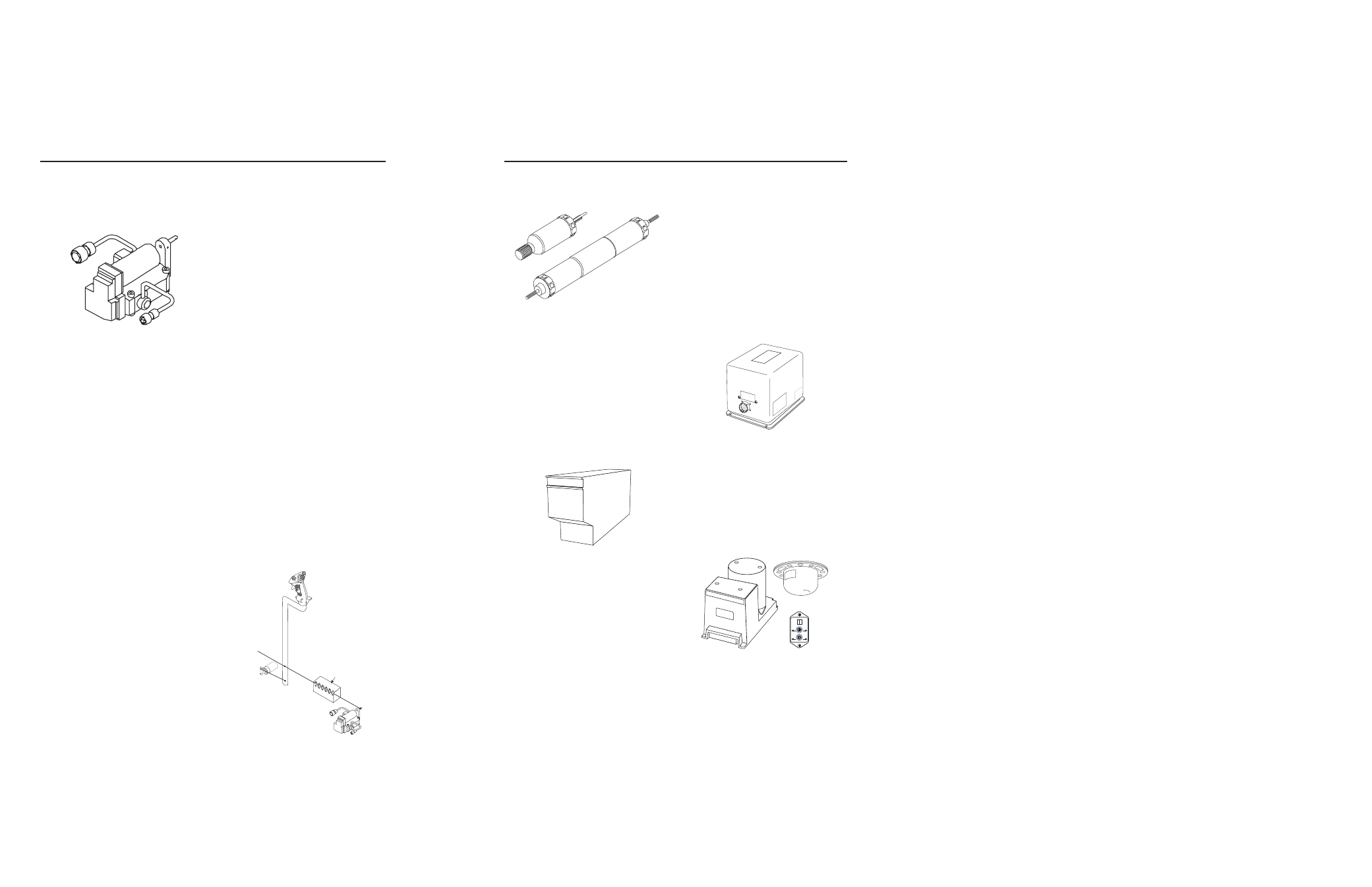
KSM 575 Linear Actuator
Assemblies
Dual KSM 575 Linear Actuator
assemblies are installed in pitch and
roll, with a single KSM 575 assembly
in yaw (anti-torque) axis of heli-
copter. The linear actuator is placed
in series with the control rods to pro-
vide limited authority high speed
damping of the helicopter. The linear
actuator contains a position trans-
ducer for feedback of actuator posi-
tion to the Flight Computer.
KCP 520 Flight Computer
Dual identical KCP 520 Flight
Computers provide all of the com-
mand computation for SCAS and
autopilot as well as the single flight
director. Each KCP 520 houses four
microprocessors. Two (redundant)
Autopilot processors provide the
autopilot control computations and
autopilot/stability augmentation
mode logic, a dedicated processor
for Flight Director provides command
computation and a dedicated
Maintenance processor assists in
diagnostics and maintenance. Inputs
to each Flight Control Computer
include control position feedback
from the control position transducers,
and Attitude, Directional, and Rate
information from the vertical, direc-
tional and rate gyros and accelera-
tion from the acceleration sensors.
The selected KCP 520 outputs servo
drive to move the linear and trim
actuators.
AFCS Sensors
KVG 350 Attitude Gyro
Dual KVG 350 Vertical Gyros pro-
vide attitude information to EFIS and
each KCP 520 Flight Computer. The
attitude information received by the
Flight Computers is used for compu-
tations and system monitoring.
KCS 305 Slaved Compass
System
The KCS 305 Slaved Compass
System is comprised of the KSG 105
Directional Gyro, the KA 51B
Slaving Accessory, and the KMT 112
Flux Valve. The slaved compass sys-
tem provides magnetic heading infor-
POSITION
SYNCHRO
CYCLIC
FORCE
GRADIENT
SPRING
DETENT
SWITCH
INSIDE
TO
LINEAR
ACTUATOR
TRIM SERVO/
MAG BRAKE
Pitc
h/ Roll Dual Ser
vo
s
Ya
w Single Ser
vo
MAN
CW
AUTO
CCW
-
+
KSG 105
1
KCP 520
ı
Flight Control System Components
(SCAS, Autopilot, and Flight Director)