BendixKing KMD 540 - Addendum System KMD 850 User Manual
Page 63
50
Revision 6 Feb/2009
KMD 550/850 FIS Addendum
Normal Operation
GRAPHICAL AIRMETS PAGE
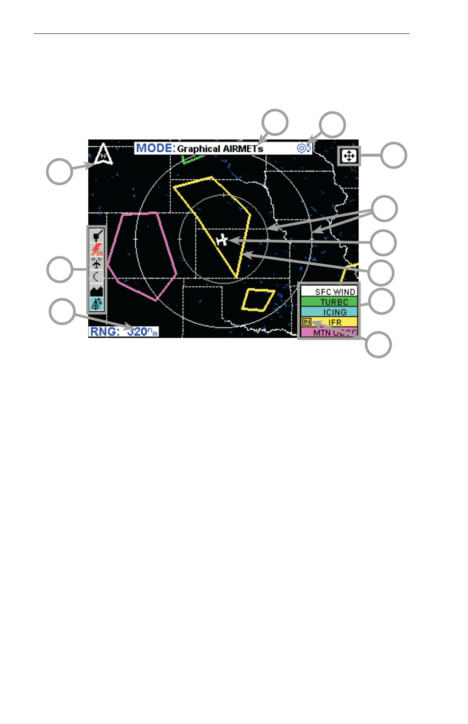
The following illustration describes the Graphical AIRMETs display. The
only difference between VDL and XM is the Datalink Wx Status icon.
1 Range Scale - Indicates selected range.
2 Available Functions - Displays icons representing data available (black)
and displayed (color).
3 North Pointer - Indicates north.
4 MODE - Indicates the weather product being displayed.
5 Control Knob Icon - Displayed when the Control Knobs are available for
cycling through the graphical weather products.
6 Joystick Label - Indicates joystick is active and can be used to pan map.
7 Range Rings - Outer ring radius is selected range and inner ring radius
is one half the selected range.
8 Aircraft Symbol - Indicates present aircraft position and heading (if
available) or track.
9 AIRMET Boundary - Color coded line indicating the boundaries of an
AIRMET.
10 AIRMET Color Key - Colors indicating AIRMET type.
11 IN - Indicates the current aircraft position is ìIN ” an IFR AIRMET.
4
2
9
6
5
1
3
7
8
10
11