Rane NM 84 User Manual
Page 17
Manual-17
Memory Recall Port
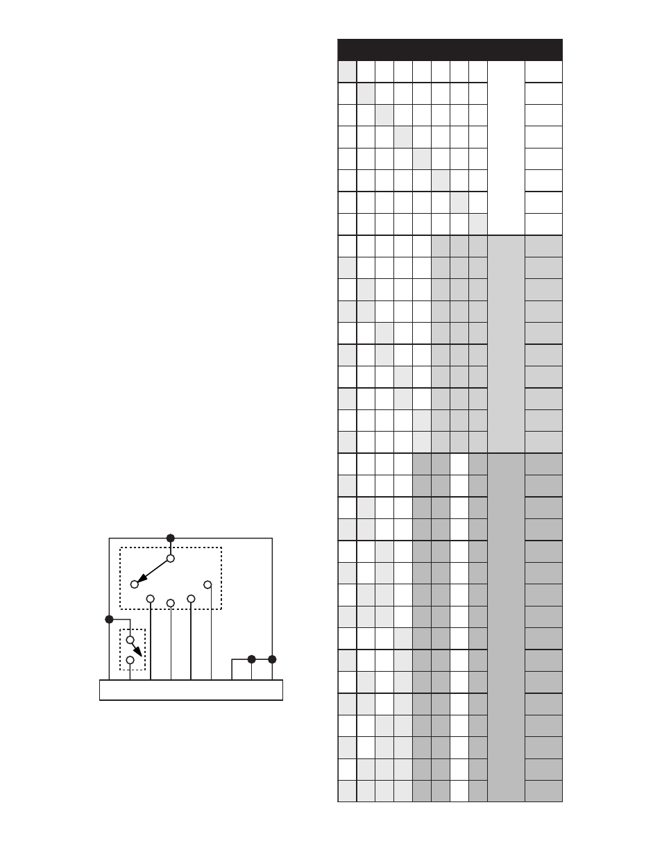
The MEMORY RECALL PORT (MRP) provides contact
closure control to recall any of the 16 Memories. Eight of the
Memories are recalled with individual switch closures to a
single terminal (see the Normal section of Table 1). Memories
in multiple units may be recalled by either connecting the
MRP terminals in parallel or by transmitting the MRP contact
closure over the network. See the Memory Edit Page section
of this manual.
Rane Firmware version 1.01 functions as follows: Only
momentary switches should be used since only single closures
are recognized. The NM 84 MRP is not read after power up,
therefore, changes to the switch states will not be updated
until the MRP conditions are changed when the power is on.
If more than one terminal is grounded at a time, only the first
closed switch is recognized. Subsequent switches are ignored
once the first switch is and remains closed. If multiple
switches are closed, once a single switch remains closed will
that memory be recalled.
However, certain combinations of terminals may be
grounded to activate Paging or Binary modes (see table). A
Binary mode allows access to all 16 Memories. For ex-
ample, connect the four contacts of a binary switch, plus the
additional Binary mode closures shown in the Table. Paging
mode provides an easy way to configure a system which uses
a single switch (such as a mic or key switch) to toggle
between two sequential Memories (See table). When wiring
contacts, only use Normal, Paging or Binary mode do not
switch between modes.
1
2
3
4
5
6
7
8
e
d
o
M
t
l
u
s
e
R
1
0
0
0
0
0
0
0
1
0
1
0
0
0
0
0
0
2
0
0
1
0
0
0
0
0
3
0
0
0
1
0
0
0
0
4
0
0
0
0
1
0
0
0
5
0
0
0
0
0
1
0
0
6
0
0
0
0
0
0
1
0
7
0
0
0
0
0
0
0
1
8
0
0
0
0
0
1
1
1
1
1
0
0
0
0
1
1
1
2
0
1
0
0
0
1
1
1
3
1
1
0
0
0
1
1
1
4
0
0
1
0
0
1
1
1
5
1
0
1
0
0
1
1
1
6
0
0
0
1
0
1
1
1
7
1
0
0
1
0
1
1
1
8
0
0
0
0
1
1
1
1
9
1
0
0
0
1
1
1
1
0
1
0
0
0
0
1
1
0
1
1
1
0
0
0
1
1
0
1
2
0
1
0
0
1
1
0
1
3
1
1
0
0
1
1
0
1
4
0
0
1
0
1
1
0
1
5
1
0
1
0
1
1
0
1
6
0
1
1
0
1
1
0
1
7
1
1
1
0
1
1
0
1
8
0
0
0
1
1
1
0
1
9
1
0
0
1
1
1
0
1
0
1
0
1
0
1
1
1
0
1
1
1
1
1
0
1
1
1
0
1
2
1
0
0
1
1
1
1
0
1
3
1
1
0
1
1
1
1
0
1
4
1
0
1
1
1
1
1
0
1
5
1
1
1
1
1
1
1
0
1
6
1
MRP Binary Control
1 = switch closed (between COM and 1,2,3,etc.)
0 = switch open
MRP Wiring
NORMAL
PAGING
BINARY
8
7
6
5
4
3
2
1
C
Mic
Switch
Memory
Switch
Paging
Mode