Rane ECM 64e User Manual
Page 10
Manual-10
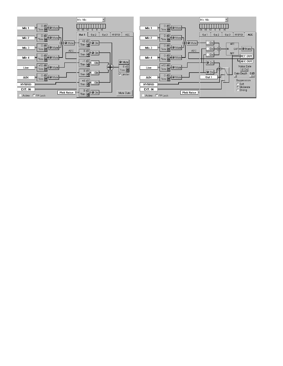
ECM 64e Input and Output Controls
Inputs
Each Input has programmable
Trim and Mute controls. The
Input
Trim operates from –15 to +16 dB in 1 dB steps. The
Input is calibrated so if it is set to 0 dB, a 0 dBu input gives a 0
dB Meter level. For a –10 dBu input, set the Input
Trim to +10
dB.
Outputs
Each Output has a programmable six-channel matrix
mixer, a programmable Output
Trim, a Mute button and a
Limiter checkbox. Unlike other systems that only have
crosspoint trims or crosspoint routing controls (like the ECB
62 and SRM 66), each Output on the ECM 64e has both
crosspoint trims and routing controls for ease and flexibility.
Each Crosspoint
Trim has a range from –15 to +16 dB in 1
dB steps and an
On/Off button for routing. The Output Trim
operates from –114 to +4 dB in 1 dB steps and is calibrated to
represent the actual level. Setting the Output
Trim to 0 dB,
with a 0 dB Meter level, produces a 0 dBu Output Level; and
setting the
Trim to 4 dB produces a +4 dBu Output Level.
The Limiter tracks the Output Trim level and engages at 5
dB above the set level. The Limiter attack rate is 10 millisec-
ond using 1 dB steps. The Limiter release rate is 50 millisec-
ond using 1 dB steps.
Acoustic Echo Canceller
The ECA 2 is an optional continually adaptive Acoustic
Echo Canceller (AEC) module (patent pending). This module
is required when the ECM 64e is used for audio teleconferenc-
ing. The ECA 2 is included in the ECM 64eAD, along with the
DH 1e. The AEC performs full-duplex audio teleconferencing
by subtracting the room loudspeaker audio from audio
received by the room microphones. This is accomplished by
routing the room loudspeaker audio to the AEC Reference
(REF.) and room microphones to the AEC IN.
The ECM 64e allows selection of different audio inputs
and reference audio feeds to create a flexible system design.
The AEC Input selects Mic Mix, Line In and Aux In, in any
combination. Most applications will require Mic Mix at a
minimum. The AEC Reference selects between Internal Mix
(consisting of Line In, Aux In and Hybrid In), Out 1 and EXT.
IN. Note: do not use Out 1 for AEC Reference if Near-End
Mics are routed to Out 1 for speech reinforcement.
Since the ECA 2 automatically adapts to the room, training
is not required.
The status of the ECA 2 can be checked in
Device >
Peripheral Status. If operating properly, the Acoustic Echo
Canceller’s Rev Level is displayed. Otherwise, Peripheral
Status displays Not Installed.
The ECM 64e provides a Noise Gate. When enabled, the
Noise Gate attenuates the AEC output by the Gate Depth
selected if no near end audio is detected. This feature is useful
in noisy room situations.
The ECM 64e also provides control over the AEC suppres-
sion. An Echo Canceller can only reduce the echo down
around the background noise of the near end room. Suppres-
sion is used to further reduce the echo. The three Suppression
choices give the installer some flexibility in matching the
ECM 64e to the room’s requirements.
Moderate will be
appropriate for most rooms.
Soft offers less Suppression and
Strong offers more. Since Suppression affects the subjective
quality of a room, experimentation is the best method to
determine which setting is best for a given room.
AEC Page