Manual- front panel: mono 3-way configuration – Rane AC 22B (2003 version) User Manual
Page 6
Manual-
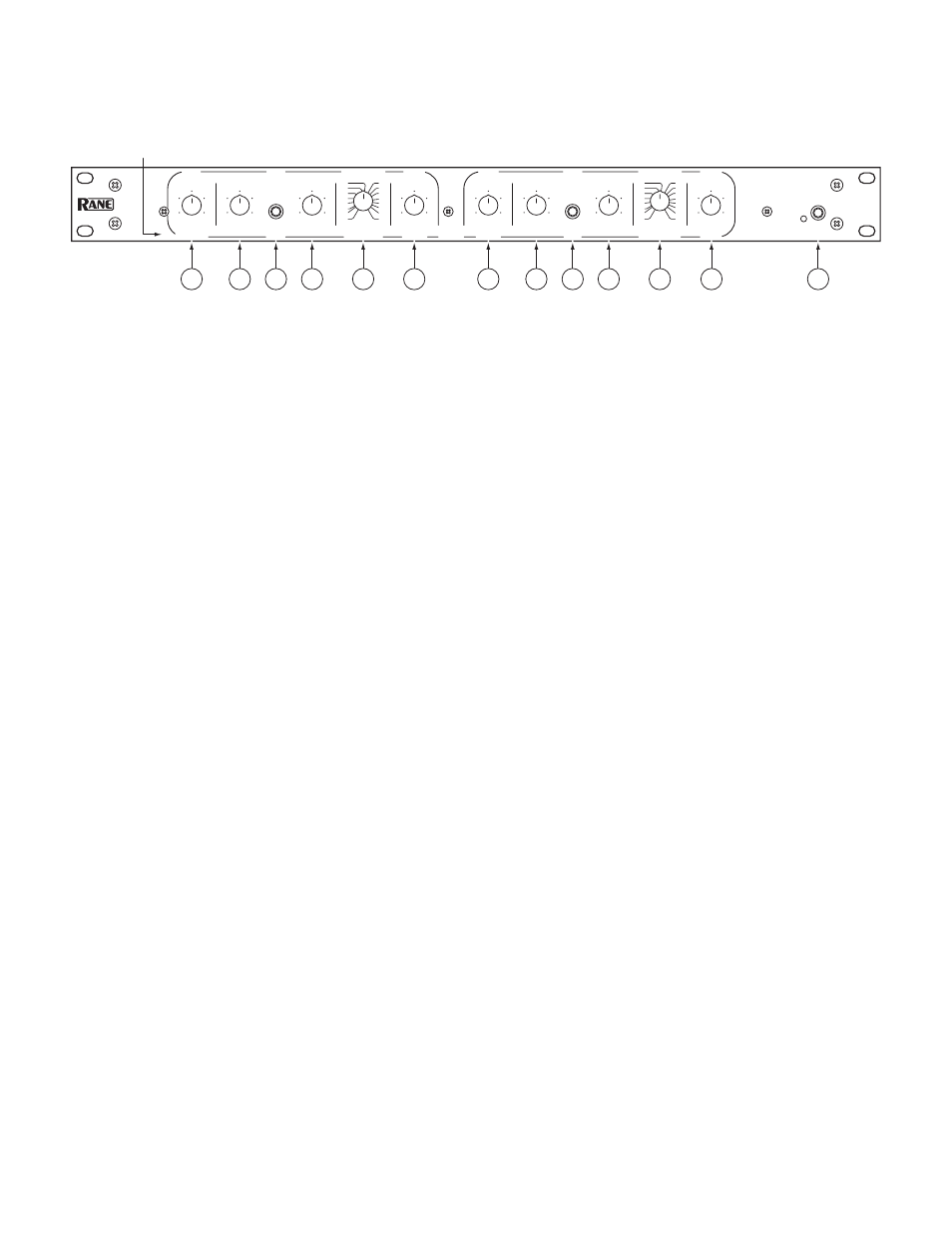
FRONT PANEL: MONO 3-WAY CONFIGURATION
Observe the labels below the controls for Mono operation.
1
CHANNEL 1 MASTER LEVEL controls the overall Level without altering the relative settings of the HIGH, MID and LOW
Outputs. Unity gain for all Level controls is at “7”.
2
LOW LEVEL controls the Level of signal going to the LOW Output.
3
LOW MUTE: When pressed to the in position, all signal is removed from the LOW Output. This eases tune-up procedure, as
described on pages Manual 7-12.
4
LOW DELAY control adds from 0 to 2 ms of time Delay to the LOW Output only. This allows a low frequency driver to be
electronically phase-aligned with a high frequency driver whose diaphragm is situated behind the low frequency diaphragm. Refer
to Time Delay Adjustment on page Manual-6 for the procedure.
5
LOW / MID FREQUENCY: This 41-detent selector determines the crossover Frequency between LOW and MID Outputs. The
detents will assure maximum accuracy and consistency between Channels. Refer to Selecting Crossover Frequencies on page
Manual-6 to determine proper setting for your particular system.
* NOTE: The Channel 1 HIGH LEVEL and Channel 2 MASTER LEVEL controls are automatically bypassed when the System Mode
switch is set to MONO 3-WAY as shown on the facing page. Adjusting these controls have no effect in MONO mode.
6
MID LEVEL controls the Level of signal going to the MID Output.
7
MID MUTE: When pressed to the in position, all signal is removed from the MID Output. This eases tune-up procedures, as
described in pages Manual 7-12.
8
MID DELAY control adds from 0 to 2 ms of time Delay to the MID Output only. This allows a mid frequency driver to be elec-
tronically phase-aligned with a high frequency driver whose diaphragm is situated behind the mid frequency diaphragm. Refer to
Time Delay Alignment
on page Manual-6 for procedure.
9
MID / HIGH FREQUENCY: sets the crossover Frequency between the MID and HIGH Outputs. Refer to Selecting Cross-
over Frequencies
on page Manual-6.
0
HIGH LEVEL controls the Level of signal going to the HIGH Output only.
q
POWER switch and indicator: Two choices: on or off. If the power supply is plugged in, this yellow LED is lit, and the POW-
ER button is depressed, then the unit ready to operate.
CH 1
MASTER
POWER
DELAY
LEVEL
LEVEL
FREQUENCY
LEVEL
LOW
MUTE
LOW / HIGH
HIGH
LEVEL
LEVEL
FREQUENCY
CH 2
MASTER
STEREO
LOW
LOW / HIGH
MUTE
HIGH
LEVEL
DELAY
AC 22B
MASTER
LOW
LOW / MID
INACTIVE
INACTIVE
MONO
MID
MID / HIGH
HIGH
10
0
2
4
8
6
10
0
2
4
8
6
10
0
2
4
8
6
10
0
2
4
8
6
10
0
2
4
8
6
10
0
2
4
8
6
MAX
MIN
2
4
8
6
MAX
MIN
2
4
8
6
ACTIVE
CROSSOVER
3.0k
70
3.6k
120
75
80
90
250
180
300
700
1.5k
2.0k
1.0k
500
400
3.0k
70
3.6k
120
75
80
90
250
180
300
700
1.5k
2.0k
1.0k
500
400
INACTIVE: MONO SUB
MONO SUB
1
2
3
4
5
*
*
6
7
8
9
10
11
Mono 3-Way labels in this row.