Manual- rear panel: stereo 2-way configuration – Rane AC 22B (2003 version) User Manual
Page 5
Manual-
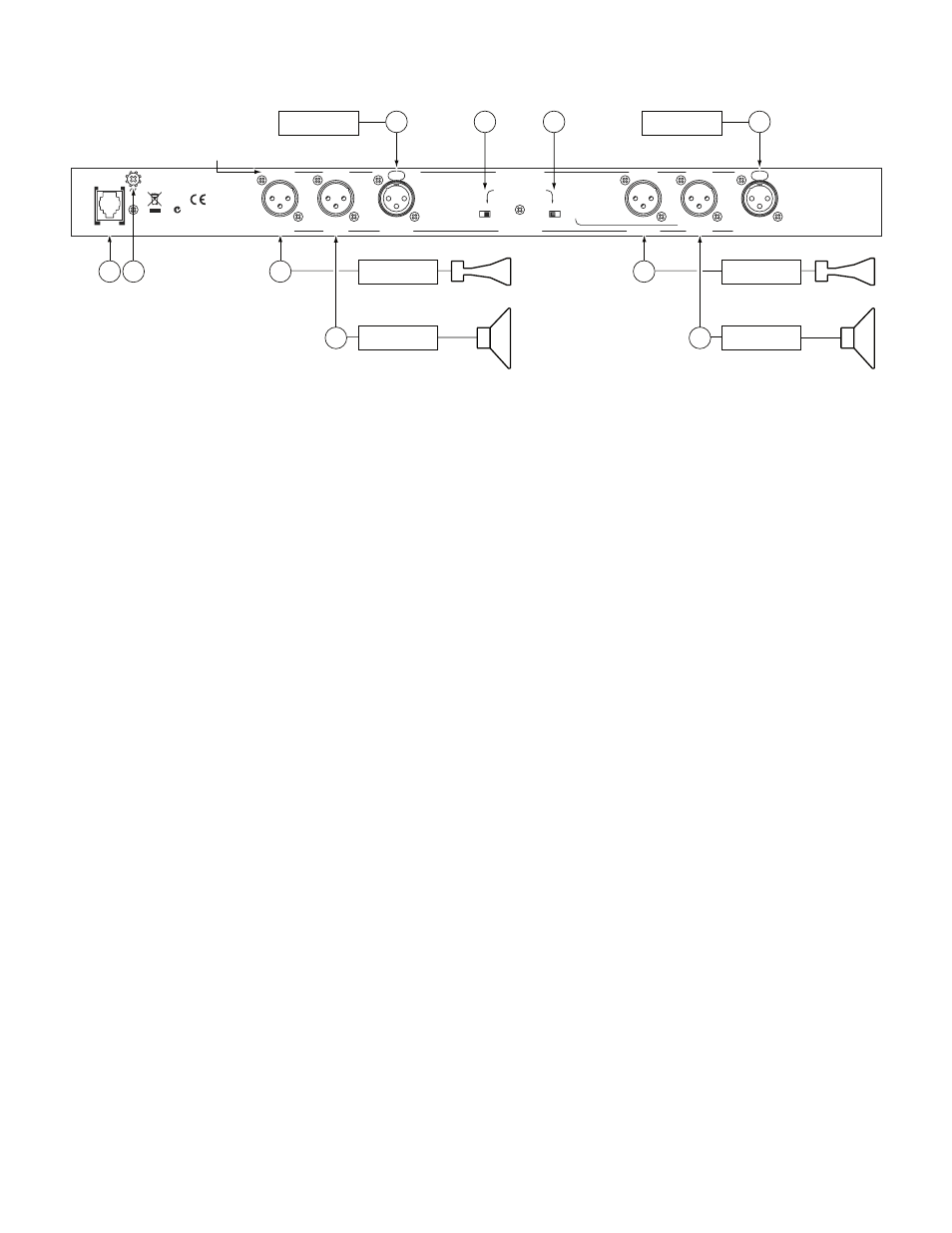
REAR PANEL: STEREO 2-WAY CONFIGURATION
Observe the labels screened above the Inputs and Outputs for stereo operation.
1
CHANNEL 1 INPUT connects to the left channel output of the mixer, equalizer or other source.
2
CHANNEL 2 INPUT connects to the right channel output of the mixer, equalizer or other source.
3
HIGH OUTPUTS: Connect Channel 1 HIGH OUT to the left channel input of the high frequency amp, and the Channel 2
HIGH OUT to the right channel input of the high frequency amp.
4
LOW OUTPUTS: Connect the Channel 1 LOW OUT to the left channel input of the low frequency amp and the Channel 2
LOW OUT to the right channel input of the low frequency amp. When using the MONO SUB switch, use Channel 1 LOW
OUT. Channel 2 LOW OUT is disconnected in MONO SUB mode.
5
SUBWOOFER switch disconnects the Output from Channel 2 LOW OUT and sums it with Channel 1 LOW OUT. The result
is taken from the Channel 1 LOW OUT.
6
SYSTEM MODE switch: Set this switch for STEREO 2-WAY operation.
7
POWER input connector: Use only an RS 1, or other remote AC power supply approved by Rane. This unit is supplied with a
remote power supply for connection to this input jack. Consult the factory for replacement or substitution. This unit’s power input
is designed for an AC supply, delivering 18-24 volts, from a center-tapped transformer capable of supplying at least the current
demanded by this product. Using any other type of supply may damage the unit and void the warranty.
8
Chassis ground point: A #6-32 screw is supplied for chassis grounding purposes. Units with external power supplies do not
ground the chassis through the line cord. In case of a grounding problem, try connecting crossover chassis ground to amplifier
chassis ground or directly to the grounding screw on a grounded AC outlet cover by means of a wire secured on both ends with
star washers to guarantee proper contact.See the Chassis Grounding Note below.
MADE IN U.S.A.
RANE CORP.
ACN 001 345 482
LOW OUT
CHANNEL 1 IN
MONO 3-WAY
MONO SUB OUT
LOW OUT
CLASS 2 EQUIPMENT
HIGH OUT
STEREO 2-WAY
SUBWOOFER SWITCH MUST
BE SET TO 2-CHANNEL
FOR MONO 3-WAY
CHANNEL 2 IN
LOW OUT
HIGH OUT
2-
CHANNEL
SUBWOOFER
MONO SUB
OMIT MONO
MONO 3-WAY
SYSTEM MODE
STEREO
2-WAY
OMIT MONO
MONO
3-WAY
OMIT FOR MONO SUB
MID OUT
HIGH OUT
AC 22B
160mA
POWER
PIN 2=POSITIVE
PIN 3=NEGATIVE
PIN 1=CHASSIS GND
Stereo 2-Way labels in this row.
3
3
7 8
High Amp
Right Input
Low Amp
Left Input
4
1
6
5
2
High Amp
Low Amp
4
IMPORTANT NOTE
CHASSIS GROUNDING
If after hooking up your system it exhibits excessive hum or buzzing, there is an incompatibility in the grounding configuration
between units somewhere. Your mission, should you accept it, is to discover how your particular system wants to be grounded. Here
are some things to try:
1. If your equipment is in a rack, verify that all chassis are tied to a good earth ground, either through the line cord grounding pin or
the rack screws to another grounded chassis.
2. Units with outboard power supplies do not ground the chassis through the line cord. Make sure that these units are grounded
either to another chassis which is earth grounded such as an amplifer, or directly to the grounding screw on an AC outlet cover by
means of a wire connected to the grounding screw on the chassis.
3. Try moving the device away from high magnetic field sources, such as large transformers used in power amplifiers.
4. Be sure of properly balanced inputs and outputs. Connect balanced devices with balanced connectors and cables. Runs longer than
10 feet (3 meters) require balanced interconnect.
Refer to RaneNote “Sound System Interconection” for more information on system grounding and balanced/unbalanced connections.