Step, Fence transmitter indicator light status table, 7a 7b – Petsafe YardMax™ Rechargeable In-Ground Fence™ User Manual
Page 17: 7d 7c
www.petsafe.net 17
13. Turn the Fence Transmitter ON. The Indicator Light on the Transmitter should illuminate to green indicating a
properly installed boundary loop. If the alarm sounds and Warning Light illuminates red, check the connections
to make sure there isn’t an open circuit. If still not operating correctly, refer to the “Troubleshooting” section in
this guide.
Fence Transmitter Indicator Light Status Table
Status Light
Condition
Solid Green
Power On
Red
Boundary Wire Broken/Disconnected
None
Transmitter is OFF or Power is Disconnected
Verifying Transmitter Boundary Wire
Connection using Receiver Collar
With the Boundary Wire in place and properly connected and the Receiver Collar fully charged, it is time to test the
system. This step needs to be completed for both YardMax
®
and Traditional Modes.
• The Receiver Collar should NOT be on your dog when the system is tested. Your pet may receive an
unintended correction.
• To prevent an unintended correction for your pet, test the boundary location and width after any change.
Testing the system ensures you have signals in proper direction to contain your pet. If wire is reversed, go back
to Fence Transmitter and swap the wires going into red and black connectors.
1. Power the Fence Transmitter ON.
2. Set Fence Transmitter Mode (A/B) Switch to A
(YardMax
®
mode)
3. Set the Boundary Width Dial on the Fence
Transmitter to 3.
Note: The numbers on the Transmitter
Boundary Width Dial indicate signal strength
and not a boundary width measurement.
4. Select a section of straight Boundary Wire that
is at least 50 feet long.
5. Set Receiver Collar to Correction Level 6 (refer
to Step 3).
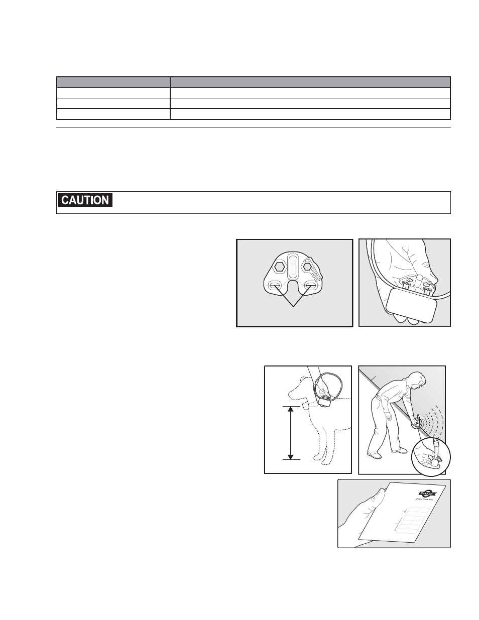
6. Place the Test Light Tool Contacts on the
Contact Points of the Receiver Collar (7A, 7B).
Test Light Contacts
7A
7B
7. Hold the Receiver Collar with the Contact Points
pointing up (7C) on the receiver facing the Boundary
Wire.
8. Start inside the Pet Area approximately 5 feet from
the Boundary Wire. Test the Boundary by approaching
and crossing the boundary wire as shown (7D). As you
cross the wire, you will hear the Warning Tone and see
the test light flash as you continue to walk further. If
you don’t hear the warning tone, turn around and walk
back across the Boundary Wire into the Pet Area to see
if it tones in that direction as the wire may be reversed.
If so, reverse the wires at the connector to the Fence
Transmitter. Do not adjust the wires connected to the
Boundary
Wire
7D
7C
Surge Protector. Then, repeat the test.
9. After verifying Receiver Collar operation at the boundary, use the labels
(7E) to identify the wire connections to the Fence Transmitter and the
Surge Protector. This will be convenient to have should any of the wires
become disconnected.
Red
Black
Loop Right
Loop Left
TX Left
TX Right
402-027
Red
Black
Loop Right
Loop Left
TX Left
TX Right
After verifying Receiver Collar
operation at the boundary, use the
labels to identify the Boundary Wire
connections to the Transmitter and
the Boundary Wire connections
to the Surge Protector. This will be
convenient to have should any of the
wires become disconnected.
Use on
Transmitter
Connections
Use on
Surge
Protector
Connections
7E
Step
7