Install the surge protector & connect the wires, Step, Additional boundary wire – Petsafe YardMax™ Rechargeable In-Ground Fence™ User Manual
Page 16: Surge protection
16
Customer Care Center 1-800-732-2677
Additional Boundary Wire
Extra direct burial Boundary Wire can be purchased in 500 foot spools
at the store where you purchased the kit or through the Customer
Care Center.
Note: When adding wire, it must act as a continuous loop.
The table at right indicates the approximate length of Boundary Wire
needed for a square, Single Loop layout. Length will vary due to the
amount of twisted wire and layout used.
Acres
Feet of Wire Needed
1/4
415
1/3
480
1/2
590
1
835
2
1180
5
1870
10
2800
Install the Surge Protector & Connect the Wires
Surge Protection
Lightning strikes that occur even several miles away from your installation can create power surges or spikes which
may damage your unprotected electronic pet containment system. The Surge Protector included with this system is
designed to protect your YardMax
™
Rechargeable In-Ground Fence
™
from surges or spikes that can reach it via your
AC power connection and/or Boundary Wire.
• Do not install, connect, or remove your system during a lightning storm. If the storm is close enough for you to
hear thunder, it is close enough to create hazardous surges.
• Risk of electric shock. Use the Fence Transmitter and Surge Protector indoors in dry location only.
• Turn off power to the outlet before you install or remove your Surge Protector.
• Risk of electric shock or fire. Use Surge Protector only with a duplex outlet with center screw.
• Do not install the Surge Protector if there is not at least 30 feet (10 meters) or more of wire between the electrical
outlet and electrical service panel.
• If possible, DO NOT use an AC circuit protected with a GFCI (ground fault circuit interrupter). Both the Surge
Protector and the fence system will function. However, in rare cases, nearby lightning may cause the GFCI to trip.
Without power, your dog may escape. You will have to reset the GFCI to restore power to the system.
• Plug the Surge Protector into a grounded (3-prong) outlet within 5 feet of the Fence Transmitter. ALWAYS use a
grounded (3-prong) outlet to ensure protection.
• Do not remove the ground prong from the Surge Protector plug. Do not use a 3-prong plug to 2-prong outlet
converter. Doing so will make the Surge Protector ineffective against surges or spikes.
• For added protection, when unused for long periods of time or prior to thunderstorms, unplug from the wall outlet
and disconnect the Loop Boundary Wires. This will prevent damage to the Transmitter due to surges.
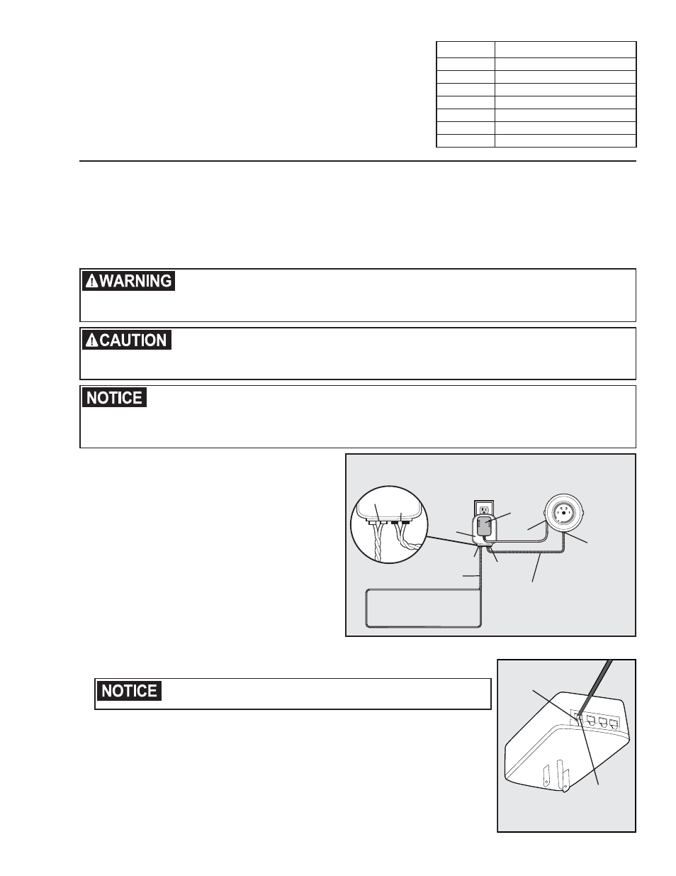
1. Turn the power OFF to the outlet to which the
Surge Protector and Fence Transmitter are
connected (6A).
2. Remove the outlet center screw that holds the cover
plate in place.
3. Plug the Surge Protector into the lower outlet.
4. Secure the Surge Protector to the outlet and cover
plate using the long screw provided.
5. Run the Boundary Wire through a window, under
a door, through a crawl space vent, or any other
appropriate available access. You can also drill a
hole through your wall.
6. Strip
3
⁄
8
inch of insulation from the ends of the
Boundary Wire.
7. Insert the stripped ends into the 2 left red
Fence Transmitter
Power
Adapter
Red Loop Tabs
Boundary Wires
(Twisted)
Boundary
Wire
Terminals
Transmitter
Wires
(Twisted)
Boundary Wire
Loop
Black
Transmitter
Tabs
LP-4100
Power
Jack
Transmitter
Loop
1
A
B
10
2
5
6
7
8
9
4
3
6A
connector holes on the bottom of the Surge Protector labeled “Loop” (6B).
8. Depress the plastic tab, insert the wires and release the tab. Make sure the wires
do not touch each other at the terminals.
Verify that the boundary loop and transmitter wires connect to the
proper Surge Protector terminals. Reversed connections will result in an
increased risk of surge related damage.
9. Determine the length of wire needed to pass from the Surge Protector to
the Fence Transmitter. Measure and cut 2 lengths of wire, then strip
3
⁄
8
inch of
insulation at both ends. Twist the 2 lengths together, with at least 10-12 twists per
foot, so the wires will not send out a signal.
10. Insert the ends of the twisted transmitter wires into the right 2 black connectors
at the bottom of the Surge Protector labeled “Transmitter”.
11. Push the tab on the Fence Transmitter to insert the opposite ends of the twisted
wire into the Loop Wire Terminals.
12. Plug the Fence Transmitter power adapter into the outlet on the front of the
Surge Protector.
LOOP TRAN
SMITTER
Push Tab
Down
Insert bare end
of wire into
opened slot
and release tab
to lock.
6B
Step
6