Nexen FMCE-875 801474 User Manual
Page 5
5
FORM NO. L-20168-D-1112
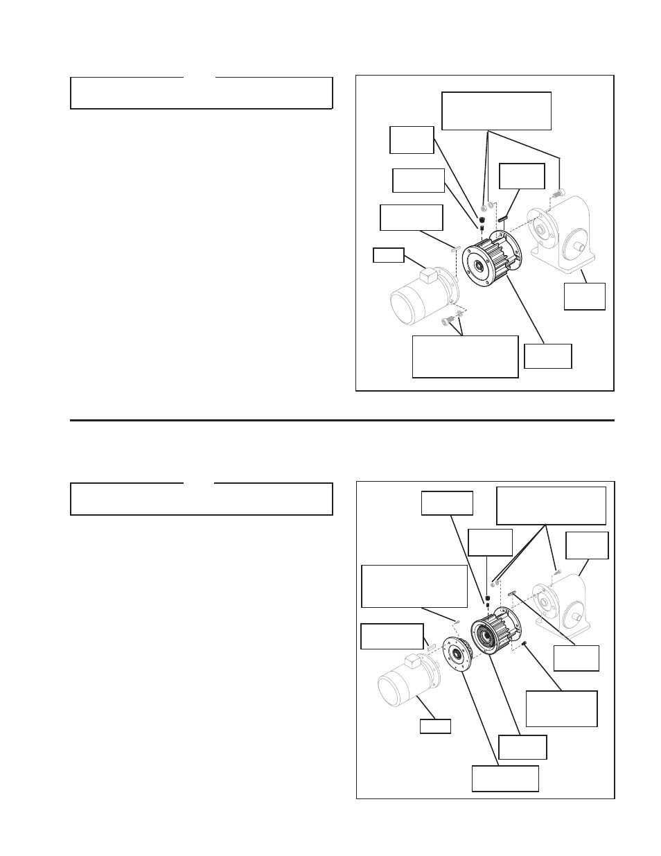
Motor
FMCE
Housing
Customer
supplied key
Gear
Reducer
Key
(Item 25)
Customer supplied
socket head cap screws,
lock washers, and nuts
Plug
(Item 27)
Set Screw
(Item 26)
FIGURE 3
FMCE 625 MOUNTED BETWEEN A GEAR REDUCER AND A MOTOR
FMCE 875, 1125, AND 1375 MOUNTED BETWEEN A GEAR REDUCER AND A MOTOR
NOTE
Align the air inlet on the FMCE, to a down position to allow
condensation to drain out of the air chamber.
1. Insert the Key (Item 25) into the output shaft of the FMCE
(See Figure 3).
2. Slide the FMCE output shaft into the gear reducer (See
Figure 3).
3. Secure the FMCE to the gear reducer using customer
supplied socket head cap screws, lock washers, and nuts
(See Figure 3).
4. Insert the customer supplied key into the motor shaft keyway
(See Figure 3).
5. Slide the motor into the FMCE and secure it to the
FMCE using Nexen supplied Socket Head Cap Screws
(Item 29) and Lock Washers (Item 30) (See Figure 3).
6. Alternately and evenly tighten the Socket Head Cap Screws
(Item 29) to 580 In. Lbs. [65.0 N•m] torque.
7. Align the Set Screw (Item 26) in the Drive Disc (Item 4) with
the hole in the FMCE Housing (See Figure 3).
8. Tighten the Set Screw (Item 26); then, install the Plug (Item
27) (See Figure 3).
Customer
supplied key
Motor
FMCE
Housing
Gear
Reducer
Key
(Item 25)
Customer supplied
socket head cap screws,
lock washers, and nuts
Set Screw
(Item 26)
Customer
supplied
socket head
cap screws
FIGURE 4
Socket Head
Cap Screws
(Item 24)
Female Pilot
(Item 13)
NOTE
Align the air inlet on the FMCE, to a down position to allow
condensation to drain out of the air chamber.
1. Insert the Key (Item 25) into the output shaft of the FMCE
(See Figure 4).
2. Slide the FMCE output shaft into the gear reducer (See Figure
4).
3. Secure the FMCE to the gear reducer using customer
supplied socket head cap screws, lock washers, and nuts
(See Figure 4).
4. Insert the customer supplied key into the motor shaft keyway
(See Figure 4).
5. Remove the Socket Head Cap Screws (Item 24) and the
Female Pilot (Item 13); then, secure the Female Pilot to
the motor face using Nexen supplied Socket Head Cap
Screws(Item 29) and Lock Washers (Item 30); then,
alternately and evenly tighten the Socket Head Cap Screws
to the recommended torque (See Figure 4 and Table 2).
6. Slide the Female Pilot (Item 13) onto the motor shaft (See
Figure 4).
7. Apply a drop of Loctite
®
242 to the threads of the Socket
Head Cap Screws (Item 24) (See Figure 4).
Socket Head
Cap Screw (Item 29)
and
Lock Washer (Item 30)
Socket Head
Cap Screw (Item 29)
and
Lock Washer (Item 30)
Plug
(Item 27)