Nexen RPS4014G-B0192T/023-EP2U 966725 User Manual
Page 8
FORM NO. L-21198-A-1204
8
A
A & B
A
Linear
Guide
Linear
Guide
Rack
Rack
Rack
Parallel
Surfaces
Shaft
Shaft
Servo Motor
Assembly
Linear
Guide
B
Tolerances Allowed In Roller Pinion Setup*
A dimensions must be Parallel ± 0.03 mm [0.001 in]
B dimensions must be Perpendicular ± 0.03 mm [0.001 in]
*Reference surfaces shown in tolerance key must be parallel and
perpendicular to each other within the specifications given. See
below for some additional setup options.
Rack and rail mounting surfaces must be flat within ±0.03 mm
[±0.001 in]
Parallel
Rack
90°
Pinion
Shaft
This distance must remain
constant throughout the
length of the rack.
PROPER SYSTEM ALIGNMENT
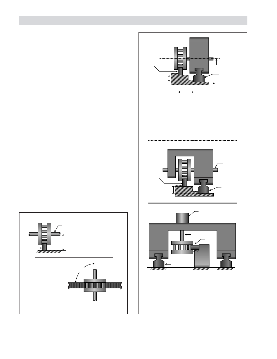
Figure 8
Possible Mounting Configurations
In order to eliminate backlash and minimize wear on the
rack, the RPS system must be installed on a straight/flat
mounting surface with the shaft parallel (±0.03 mm
[0.001in] to the mounting surface and perpendicular to
the rack length.
The following requirements must be met to ensure level
mounting and proper RPS operation:
a)
Mount a linear guide rail on a surface parallel to the
RPS Rack mounting surface with the same flatness
and grade as the rack mounting surface (Refer to
Figure 8).
b)
The Pinion Shaft must be parallel (±0.03 mm
[0.001 in]) to the mounting surface and the angle
between the Pinion Shaft and the rack must be
exactly 90° (Refer to Figure 7).
c)
The Pinion Shaft must be supported adequately to
ensure full contact of roller pins along the face of
rack teeth.
A
LIGNMENT
V
ERIFICATION
Proper tooth engagement can be verified by applying
machinists blueing to the pinion rollers and rolling the pin-
ion down the length of the rack. The contact pattern should
be even across each tooth face when the pinion is prop-
erly aligned.
Figure 7
Alignment Requirements
Systems may be mounted in any angle as long
as the rack, guiding system and mounting
surface remain parallel with the shaft at a 90°
angle from the rack.