Nexen RPS4014G-B0192T/023-EP2U 966725 User Manual
Page 7
7
FORM NO. L-21198-A-1204
ROLLER PINION SETUP
NOTE: Refer to sales drawings for shaft details.
NOTE: Refer PROPER SYSTEM ALIGNMENT and Fig-
ures 6 & 7 for Roller Pinion mounting requirements.
NOTE: Pinion should be mounted as close to a bearing
as possible for optimal performance.
1.
Remove any debris from the shaft, roller pinion and
mechanical lock.
NOTE: The RPS is shipped with the mechanical lock
already inserted into the roller pinion bore.
2.
If the mechanical lock has been removed, insert the
cylindrical wedge into the roller pinion bore until it
rests against wall of the roller pinon.
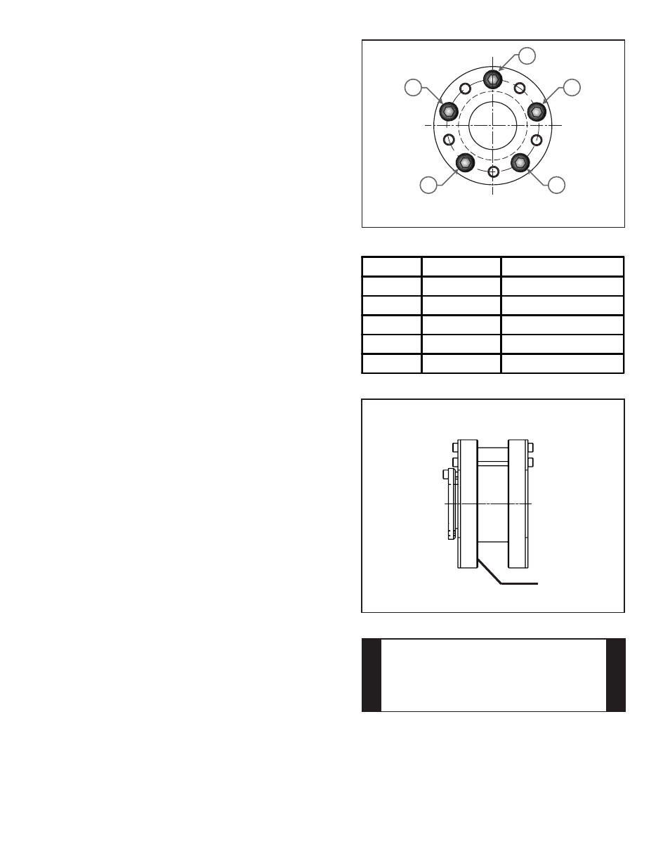
3.
Insert the inner race of the mechanical lock into the
roller pinon bore with one screw hole in the 12 o-
clock position (See Figure 5).
NOTE: Ensure that the slots in the two components
that make up the mechanical lock are not aligned.
4.
Insert the shaft into the bore.
5.
Insert the lock bolts into the through holes
(threaded holes are for mechanical lock removal).
6.
Hand tighten the lock bolts.
7.
Equally tighten the lock bolts with 1/4 of the
recommended tightening torque. Start tightening at
the top bolt and alternate back and forth across the
face in a star pattern until all five bolts are
tightened (Refer to Figure 5 and Table 3).
8.
Finally, tighten the lock bolts at the predetermined
torque using a torque wrench.
Progressive tightening of the lock bolts is important
to prevent any misalignment of components while
installing the mechanical lock.
NOTE: Runout is minimized if a Dial Indicator is used
as the lock bolts are tightened. Place the contact tip of
the Dial Indicator on a smooth surface to measure
runout (See Figure 6). Runout on this surface must be
± 0.13 mm [±0.005 in] TIR when lock bolts are tightened.
NOTE: Allow pinion to travel along the rack, making
sure the sides of the rack do not contact the sides of
the pinion.
1
4
3
5
2
Figure 5
Mechanical Lock Front Face
Model
Bolt Type
Tightening Torque
RPS16
M4
3.5 Nm [30.98 in-lb]
RPS20
M5
7.0 Nm [61.96 in-lb]
RPS25
M6
12.0 Nm [106.21 in-lb]
RSP32
M6
12.0 Nm [106.21 in-lb]
RPS40
M6
12.0 Nm [106.21 in-lb]
Table 3
CAUTION
Preload must be applied before putting
Preload must be applied before putting
Preload must be applied before putting
Preload must be applied before putting
Preload must be applied before putting
your system into operation. Refer to
your system into operation. Refer to
your system into operation. Refer to
your system into operation. Refer to
your system into operation. Refer to
APPL
APPL
APPL
APPL
APPLYI
YI
YI
YI
YI N
N
N
N
N G PR
G PR
G PR
G PR
G PR E
E
E
E
E L
L
L
L
LO
O
O
O
OAD to properly set
AD to properly set
AD to properly set
AD to properly set
AD to properly set
preload for your R
preload for your R
preload for your R
preload for your R
preload for your RPS system.
PS system.
PS system.
PS system.
PS system.
Figure 6
Measure runout
on pinion face