Installation, Rack mounting dimensions – Nexen RPS4014G-B0192T/023-EP2U 966725 User Manual
Page 4
FORM NO. L-21198-A-1204
4
Rack
Model
rack
length
A
B
C
D
E
F
G
H
J
K
L
Through
Hole
Tapped Hole
Thread Depth
RPS16
half rack
80
[3.15]
32 [1.26]
24 [0.94]
8
[0.31]
24
[0.94]
8
[0.31]
9
[0.35]
M6
12
[0.47]
M8
M6 x 50
9
[0.35]
M8
full rack
32 [1.26]
24 [0.94]
RPS20
half rack
80
[3.15]
20 [0.79]
10 [0.39]
10
[0.39]
30
[1.18]
10
[0.39]
11
[0.43]
M8
16
[0.63]
M10 M6 x 60
11
[0.43]
M10
full rack
40 [1.57]
30 [1.18]
RPS25
half rack
100
[3.94]
100 [3.94] 62.5 [2.46] 37.5
[1.48]
36
[1.42]
12
[0.47]
14
[0.55]
M10
20
[0.79]
M12 M10 x 75
14
[0.55]
M12
full rack
100 [3.94] 62.5 [2.46]
RPS32
half rack
100
[3.94]
112 [4.41]
56 [2.20]
56
[2.20]
44
[1.73]
16
[0.63]
14
[0.55]
M10
20
[0.79]
M12 M10 x 95
14
[0.55]
M12
full rack
92 [3.62]
36 [1.41]
RSP40
half rack
160
[6.30]
40 [1.57]
20 [0.79]
20
[0.79]
54
[2.13]
21
[0.83]
14
[0.55]
M10
20
[0.79]
M12 M10 x 95
18
[0.71]
M16
full rack
40 [1.57]
20 [0.79]
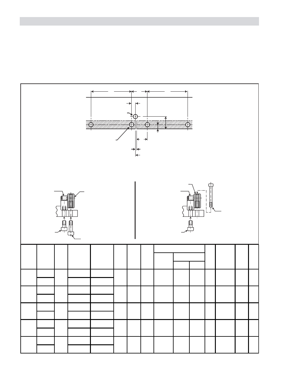
RACK MOUNTING DIMENSIONS
A
B
C
A
D
E
F
E
F
K
First Rack
Second Rack
clearance of 0.1 ~ 0.2mm
reference end surface of first rack
G*
Connecting Tool
Mounting Hole
Rack
Mounting
Hole
L
H
Rack
Mounting
Bolt
Alignment Tool
Mounting Bolt
Alignment Tool
Rack
*G
Tapped Hole Mounting of Connecting Tool
*G
Through Hole Mounting of Connecting Tool
L
J
Rack
Mounting
Bolt
Alignment Tool
Mounting Bolt
Alignment Tool
Rack
INSTALLATION
The mounting surface for both the rack and the guiding system must be parallel within the specifications shown in the
PROPER SYSTEM ALIGNMENT section. This parallelism requirement is best achieved by machining a common bed for
both the guiding system and rack in the same operation. (Refer to PROPER SYSTEM ALIGNMENT and Figures 7 & 8
for Possible Mounting Configurations.)
The system operates best when kept free from debris. Nexen recommends orienting the rack so it minimizes debris from
collecting on the teeth.
Figure 1