Nexen HGP25 969053 User Manual
Page 13
13
FORM NO. L-21277-B-1213
Table 4
Screw
Tightening Torque
Nm [in-lb]
Preloader Screw
All Models
--
1.7 [15] Max
Shoulder Screws (Mtg. Plate)
Preloader, HG17
M6 x 1.0
17.5 [155]
Preloader, HG25
M8 x 1.25
40 [354]
P
reloadinG
P
rocedure
(
continued
)
3. Verify that pinion alignment requirements are being
met, and the rack is centered between the pinion
bearing flanges as shown in Figure 3.
4. If your preload system utilizes lifting/jacking screws
to vary the amount of preload, rotate the adjustment
screws to separate the pinion from the rack, verifying
that clearance is initially present. Clearance can be
observed in the form of system backlash. Then rotate
the adjustment screws in the opposite direction to
begin seating the pinion into contact with the rack.
When a larger amount of resistance is felt, back the
adjustment screw(s) off approximately 1/8 of a turn.
This step is critical to prepare for the setting of actual
preload.
If your preload system utilizes eccentric slots or other
methods of adjustment, rotate or shift the adjusting
member as necessary to separate the pinion from
the rack, verifying that clearance is initially present.
Clearance can be observed in the form of system
backlash. Then rotate or shift the adjusting member
in the opposite direction to begin seating the pinion
into contact with the rack. When the pinion contacts
the rack, stop. This step is critical to prepare for the
setting of actual preload.
5. Place a magnetic base dial indicator on the movable
carriage, and locate its probe on the OD of the pinion
flange such that it measures in the direction of preload
travel.
6. Apply the preload of 0.010 - 0.015 mm [0.0004 -
0.0006 in] with the preload application screw(s) (or
either preload application device specific to your
preloading system) and then tighten the preload
lockdown fasteners to their recommended torques.
See Table 4 for Nexen Preloader System torque
values. Typically the preload will change slightly when
the preloader lockdown fasteners are tightened. If
tightening the preload fasteners causes the amount
of preload to fall outside of specifications, record
how much it changed when tightening the preloader
lock down fasteners, loosen the preloading system
and repeat the preloading procedure but adjust the
initial preload (more or less) by the recorded preload
deviation. This procedure will ensure that when
the preloader lockdown fasteners are tightened the
amount of preload will remain within specifications.
7. With the pinion preloaded to specifications manually
traverse the carriage down the run (if possible),
checking for smoothness and uniformity of resistance.
If manually applied motion is not possible, use the
servo motor to traverse the carriage along the run
slowly while looking and listening for resistance to
motion.
Proper roller to tooth meshing is critical and can be verified
by two methods depending on which you find easier to
interpret:
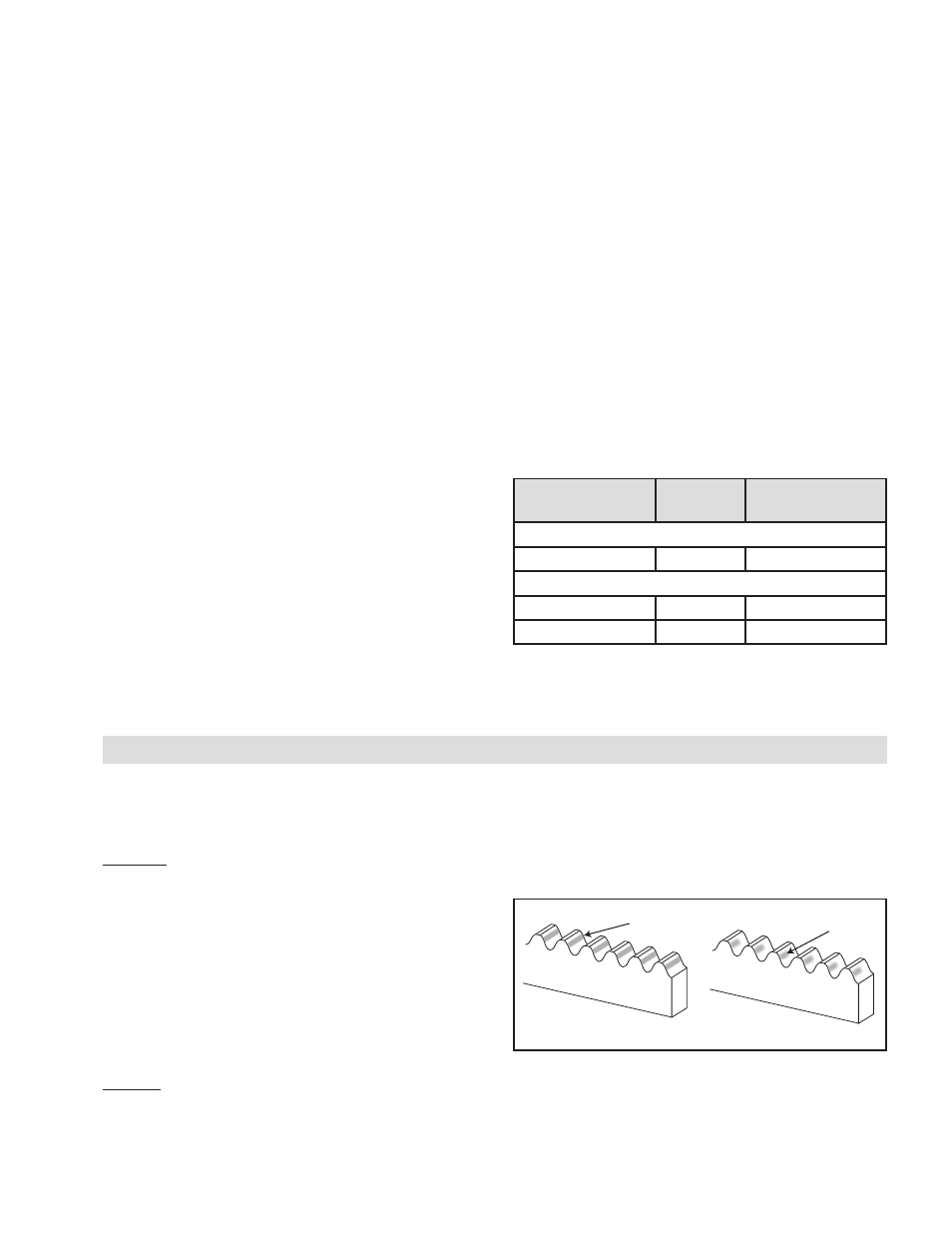
Option 1: Apply a slow drying machinists dye to the
pinion rollers and slowly move the RPS back and forth
over a short distance (about 1/2 meter). It is important the
dye remain wet so it transfers to the rack teeth and is not
depleted. Analyze the dye pattern transferred to the teeth.
If the meshing geometry is good the dye will be spread
evenly all the way across the tooth face over the middle
2/3 - 3/4 of the teeth with none at the top and bottom. If
this section is properly aligned clean off dye residue and
repeat as necessary to verify the RPS alignment over the
entire length of travel. See Figure 16.
Option 2: Apply a small amount of grease (see Lubrication
section) to each rack tooth face over 1/2 meter of rack.
Slowly move the RPS system back and forth over this
1/2 meter of travel. If the meshing geometry is good the
Good Alignment
Poor Alignment
Contact Pattern
Contact Pattern
Figure 16
grease will be completely wiped away all the way across
the tooth face over the middle 2/3 - 3/4 of the teeth with
some remaining at the top and bottom. If this section is
properly aligned clean off grease with a solvent and repeat
as necessary to verify the RPS alignment over the entire
length of travel as shown in Figure 16.
SYSTEM ALIGNMENT VERIFICATION
If the dye or grease contact pattern indicates a meshing
problem, diagnose the problem, correct it, and then
repeat the Applying Preload and System Alignment
Verification procedures.