Nexen HGP25 969053 User Manual
Page 11
11
FORM NO. L-21277-B-1213
The order in which the HGP is assembled to the
motor, preload adjustment system, machine, or initial
engagement with the RPS rack is not critical, and should
be done in whichever order provides for the least amount
of difficulty to the machine assembler.
i
nStallation
of
m
otor
to
HGP
1. Before installing the motor into the HGP:
a. Wipe the motor shaft, pilot, and mounting face
clean. Wipe the internal pilot and motor mounting
face of the HGP clean.
b. Ensure that the HGP’s clamp collar is positioned
over the slotted portion of the motor shaft bore
such that the slots do not line up.
c. Remove clamp collar access set screw.
d. Insert the long blade of a hex bit (included) through
the clamp collar screw access hole in the motor
adapter and engage with the clamp collar screw
head.
2. Apply a serviceable thread locking compound to the
threads of the motor face mounting screws and a thin
film of anti-sieze compound to the motor shaft.
3. Slowly and gently guide the motor into the input of the
HGP. During this part of the procedure, the weight
of the motor should be adequately supported. Never
allow the motor to be suspended from HGP until the
shaft and pilot diameter are fully inserted.
4. Once the motor shaft and pilot are fully seated within
the HGP input, tighten the motor face mounting
screws according to Table 3. After the motor face
screws are tightened the clamp collar screw can be
tighten, also according to Table 3.
NOTE: Once motor has been fully assembled to HGP,
remove the hex bit from the clamp collar access hole
and save for future disassembly needs.
5. Reinstall clamp collar access set screw.
i
nStallation
of
HGP
to
P
reloader
S
yStem
or
m
acHine
1. Before installing the HGP into the preloader system:
a. Wipe the HGP pilot and mounting face clean.
Wipe the internal pilot and HGP mounting face
of the adjusting member of the preloader system
clean.
b. Wipe clean and apply a light coating of oil to any
faces of the preloader system which will slide
against one another during adjustment.
c. Apply a serviceable thread locking compound to
the threads of the HGP mounting screws. If using
the Nexen Preloader System, these screws are
provided.
d. Gently guide the HGP into the adjusting member
of the preloader system. Install HGP mounting
screws, using a star pattern while tightening to
the torque values shown in Table 3. These screws
should be tightened to 25% of this value in the first
iteration of the star pattern, 50% in the second
iteration, and 100% in the final iteration.
2. If the HGP will be installed directly to the machine
frame, clean and all the piloting faces and install using
the torques described in Step 1.d above.
HGP e
nGaGement
witH
rPS r
ack
Initial engagement with the rack may be accomplished
using one or more of the following methods, as the
machine’s design allows:
• The HGP can be initially assembled to the machine.
Set the position of the preload system’s sliding
member for a small amount of clearance (backlash)
between the pinion rollers and rack teeth. The pinion
can then be rolled onto the end of a section of rack
which has been secured. Backdriving of the HGP is
permissible.
•
A section of rack within a run can be removed to allow
the pinion to roll onto an adjacent rack as described
above, and then reinstalled.
•
If sufficient travel within the preload system exists, the
HGP can be initially assembled to the machine. Adjust
the position of the preload system’s sliding member
until the pinion rollers clear the rack tooth tips. From
it’s end face, the rack can then be slid beneath the
pinion rollers and between the pinion’s bearing flanges
into position. The preloader’s position can then shift
to attain initial engagement of the pinion rollers and
rack teeth.
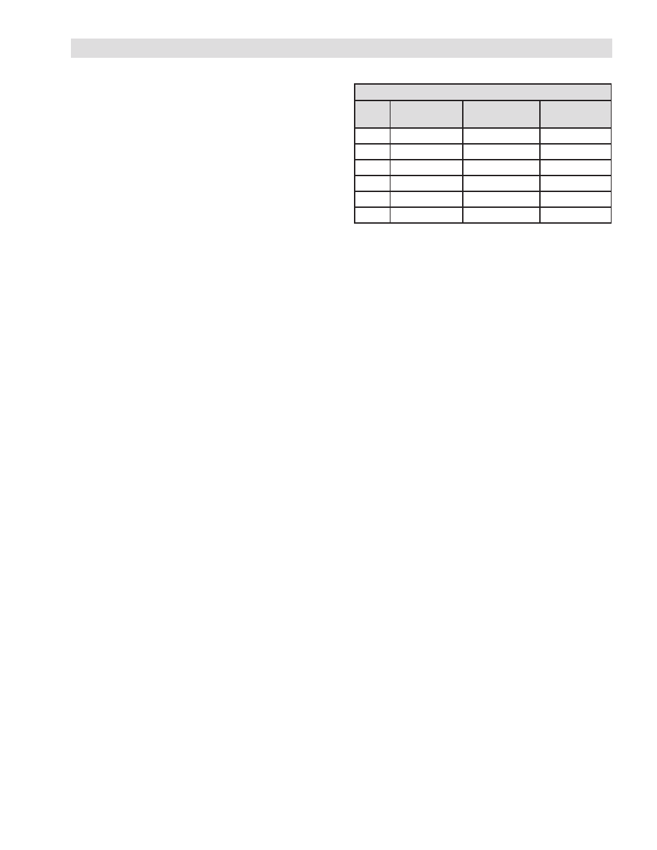
Motor Fasteners
Size
HGP Mounting
Screw Torque
Motor Mounting
Screw Torque
Clamp Collar
Screw Torque
17
32 in-lbs
28 in-lbs
18 in-lbs
25
32 in-lbs
28 in-lbs
18 in-lbs
Table 3
HGP INSTALLATION