Assembly instruction 2 / 4, Cg b, Df e – Home Styles 5217-95 User Manual
Page 2: Step 2, Step 3, Step 1
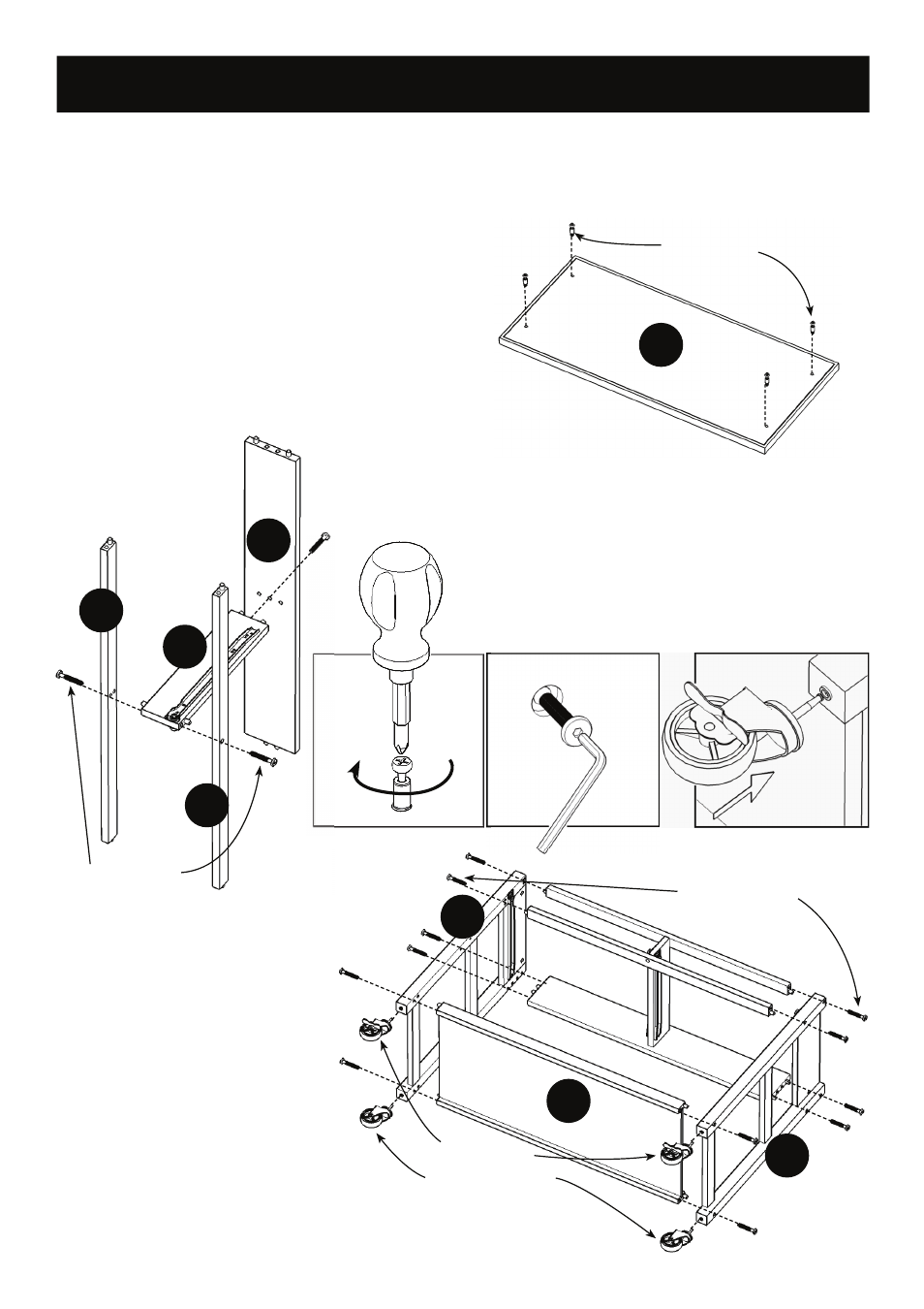
IMPORTANT
* Do not tighten up all the screws and bolts until each part is properly assembled.
* You should keep Hex Wrench in a safe place as you may need to tighten up the Head Cap Bolts in the future.
* Use a soft cloth between these parts and the fl oor.
STEP 2
Attach Front Rails (D) and Back Rail (E) to Divider (F) with
Head Cap Bolts (long). (see Figure 2)
Figure 3
Assembly Instruction 2 / 4
D
Head Cap Bolt (long)
A
STEP 3
Attach Side Frames (B) and (C) to
the unit from Step 2 and Base (G)
with Head Cap Bolts (long).
Attach 4X Casters to unit with
locking casters at the front and
non-locking casters at the back.
(see Figure 3)
C
G
B
Head Cap Bolt (long)
STEP 1
Insert Cam Lock Screws into the pre-drilled
holes of Top (A). (see Figure 1)
D
F
E
Figure 1
Cam Lock Screw
Locking Casters
Non-Locking Casters
Figure 2
- 9200-1611 (5 pages)
- 9200-1411 (5 pages)
- 9200-1211 (5 pages)
- 9200-1111 (5 pages)
- 9100-1711 (5 pages)
- 9100-1611 (5 pages)
- 9100-1411 (5 pages)
- 9100-1211 (5 pages)
- 9100-1111 (5 pages)
- 9001-0711 (5 pages)
- 9001-0611 (5 pages)
- 9001-0411 (5 pages)
- 9001-0211 (5 pages)
- 9001-0111 (5 pages)
- 5257-95 (5 pages)
- 5254-95 (5 pages)
- 5252-95 (5 pages)
- 4508-95 (5 pages)
- 5520-958 (2 pages)
- 5061-95 (4 pages)
- 5134-95 (4 pages)
- 5411-61 (3 pages)
- 5411-615 (3 pages)
- 5033-94 (6 pages)
- 5033-958 (2 pages)
- 5033-94 (2 pages)
- 5010-948 (7 pages)
- 9100-1077G (5 pages)
- 9100-1066G (5 pages)
- 9100-1071 (4 pages)
- 9100-1027G (5 pages)
- 9100-1072 (4 pages)
- 9100-1023 (4 pages)
- 9001-0066G (5 pages)
- 9001-0047G (6 pages)
- 5588-948 (2 pages)
- 5588-948 (9 pages)
- 5543-948 (2 pages)
- 5543-948 (9 pages)
- 5542-948 (2 pages)
- 5542-948 (9 pages)
- 5181-64 (5 pages)
- 5180-64 (5 pages)
- 5033-358 (1 page)
- 5020-65 (6 pages)