Bradford White U-65T-55FR-3N User Manual
Page 11
THERMOPILE REPLACEMENT
Step 1.
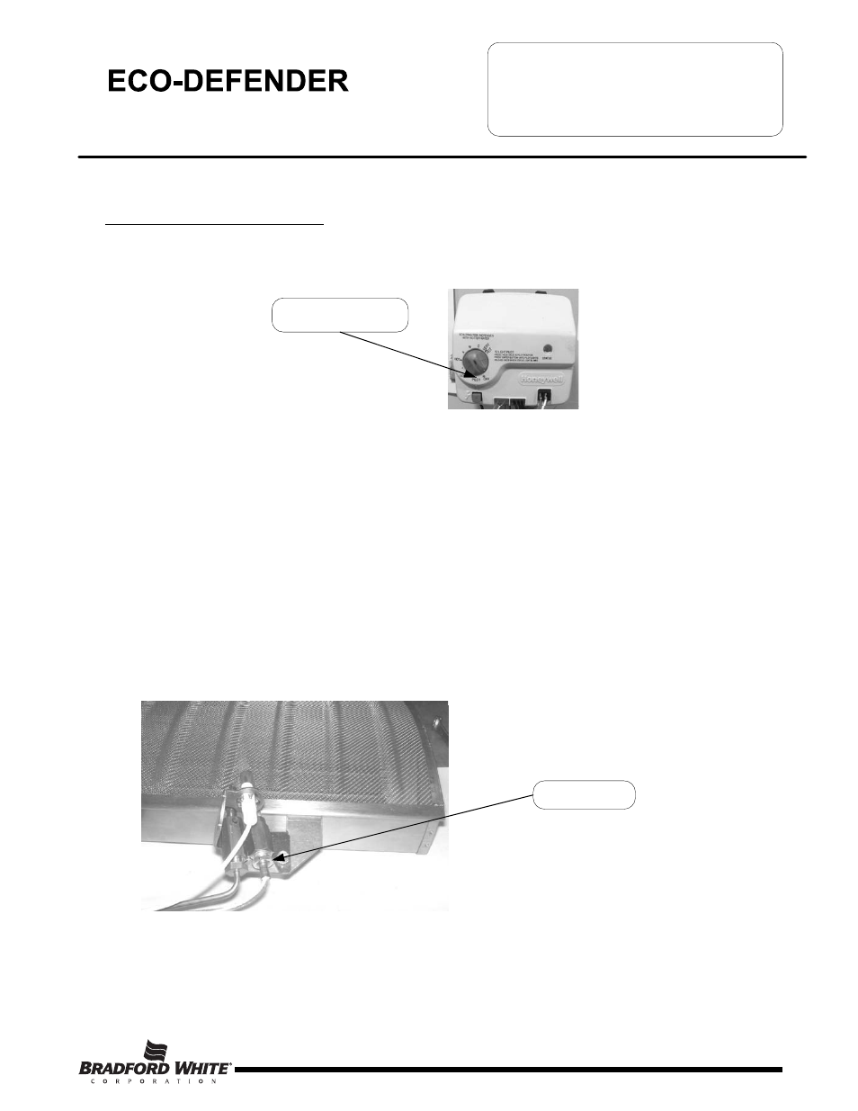
Turn off gas supply to water heater. Rotate gas control knob to the “OFF” position.
Step 2.
Remove outer jacket door.
Step 3.
Remove right side inner door and burner door per SERVICE PROCEDURE RG-I, steps 3a through 3g.
Step 4
Disconnect the red thermopile wire from the wire harness and the white thermopile wire from the resettable
thermal switch. Follow the thermopile leads to the pilot bracket. Disconnect the thermopile from the pilot
bracket (7/16" wrench).
Step 5.
Install new thermopile into pilot bracket and tighten the nut to the pilot bracket (7/16" wrench). Position
thermopile wire against left side inner door flange at its original position. Connect the red thermopile wire to
the red lead from the wire harness. Connect the white thermopile wire to the resettable thermal switch.
Step 6.
Inspect inner door gasket per SERVICE PROCEDURE ED-I, Step 4.
Step 7.
Install right side inner door and burner door per SERVICE PROCEDURE ED-I, Step 7 through Step 16.
Step 8.
To resume operation follow the instructions located on the lighting instruction label or the lighting
instructions located in the installation and operation manual.
SERVICE PROCEDURE ED-II
Thermopile Testing and Replacement
Page 11
Gas Control Knob Shown In
“OFF” Position
Thermopile Position
11