Components and connections, Front view – Vinten Radamec Head Processing Module (HPM) User Manual
Page 7
5
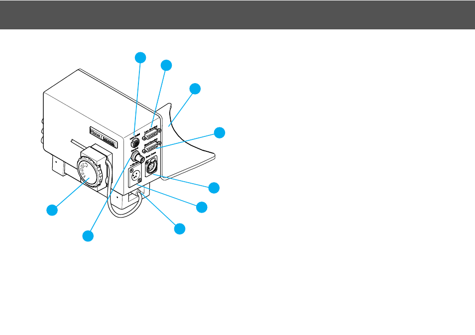
Components and Connections
Front View
1 . . . . . . . . . . . . . . . . . . . . . . . . . . . . . . . . Lens serial port
2 . . . . . . . . . . . . . . . . . . . . . . . . . . . . . Lens encoders port
3 . . . . . . . . . . . . . . . . . . . . . . . . . . Head mounting bracket
4 . . . . . . . . . . . . . . . . . . . . . . . . . . . . . Head encoders port
5 . . . . . . . . . . . . . Ethernet port (Base Coms; to pedestal)
6 . . . . . . . . . . . . . . . . . . . . . . . . .Power OUT (to pedestal)
7 . . . . . . . . . . . . PSU, power output socket (lead to HPM)
8 . . . . . . . . . . . . . . . . . . . . . . . Genlock OUT (to pedestal)
9 . . . . . . . . . . . . . . . . . . . . . . . . . . . . . . . . . . .Cable clamp
5
6
7
8
9
2
4
3
1