Connector pinout, Connector pinout 41 – ThingMagic Astra-EX User Manual
Page 41
Using GPIO
M6 and Astra-EX User Guide
41
Note
For non-isolated applications connect grounds together (pin6 and 7) and V-GPO to
M6 and Astra-EX+5V (pins 1 and 5). With this configuration the reader provides the
+5V supply and can sink up to 200mA, total.
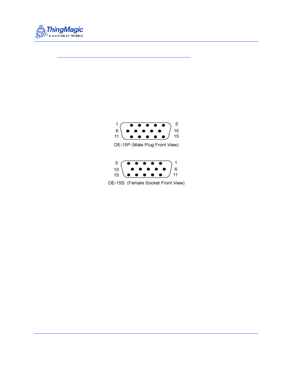
Connector Pinout
The following are the pin-outs of the 15-pin connector:
Figure 13:
DE15 GPIO Pinout
1.
M6 and Astra-EX+5V - non-isolated power from M6 and Astra-EX
2.
N/A
3.
N/A
4.
User Output 2 (GPIO_1)
5.
V-GPO - Isolated source power for outputs
6.
ISO-GND - Isolated ground for outputs
7.
M6 and Astra-EX Ground - non-isolated ground
8.
User Output 1 (GPIO_0)
9.
User Output 2 (GPIO_1)
10.
User Output 3 (GPIO_2)
11.
User Output 4 (GPIO_5)
12.
User Input 1 (GPIO_3)
13.
User Input 2 (GPIO_4)
14.
User Input 3 (GPIO_6)
15.
User Input 4 (GPIO_7)
Note:
The values in parentheses indicate the enumeration used by the MercuryAPI for each GPIO line.