Tjernlund PAI-2T Fresh Air In-Forcer (Discontinued) 8504039 Rev A 06/00 User Manual
Page 9
8
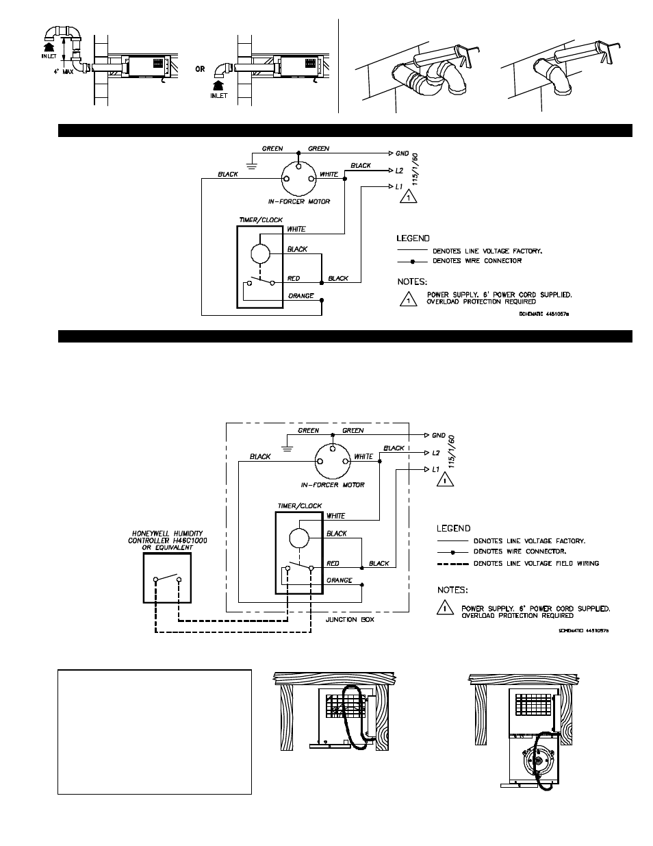
IN-FORCER PAI-T SERIES JUNCTION BOX LADDER DIAGRAM
LADDER DIAGRAM OF PAI-T SERIES WITH OPTIONAL HUMIDISTAT
The diagram below shows the PAI-T Series with an optional line voltage humidistat wired in parallel to the Timer/Clock.
All Wiring from the PAI-T Series to the humidistat must be appropriate Class 1 wiring as follows: installed in rigid metal conduit, inter-
mediate metal conduit, rigid non-metallic conduit, electrical metallic tubing, Type MI cable, Type MC cable or can be otherwise suit-
ably protected from physical damage.
NOTE:
If hard-wiring IN-FORCER into electrical
box leave approximately 10” or sufficient
slack in wiring for pull-down servicing fea-
ture of IN-FORCER, (See Diagram N).
Remove six (6) screws from bottom front
and sides of IN-FORCER while holding
blower assembly firmly. Carefully slide
blower assembly down until stops hold in
place, (See Diagram O, Page 10).
DIAGRAM M
OR
DIAGRAM L
DIAGRAM N