Tjernlund PAI-2T Fresh Air In-Forcer (Discontinued) 8504039 Rev A 06/00 User Manual
Page 7
6
INSTALLATION OF IN-FORCER
A minimum two foot length of PVC intake pipe is recommended so the IN-FORCER can be easily serviced. If intake PVC pipe
lengths are relatively short, the pipe can be cemented to the IN-FORCER coupler and fed through exterior opening before securing to
the wall. If PVC pipe run is extended, first secure IN-FORCER to joist/truss, then extend PVC pipe run through exterior opening and
cement to PVC coupler.
Note:
Before cutting opening through wall, consider layout of PVC pipe runs and confirm intake elbow termination clearances are
met as shown on page 4.
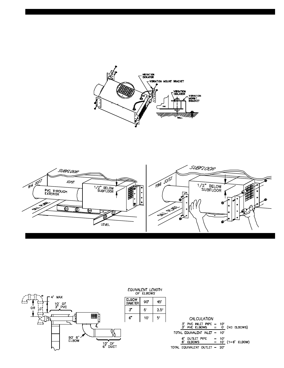
1. Assemble vibration mount brackets on IN-FORCER as shown below in diagram E.
2. Install IN-FORCER 1/2” below subfloor making sure that unit is level. NOTE: 1/2” space must be followed so PVC pipe lines up
with hole template.
3. Level IN-FORCER on underside length wise and width wise making sure it is level in both planes, (See Diagram F).
4. Once determined IN-FORCER is level, secure to wall with provided screws, (See Diagram G). Note: Drill 4 - 1/4” holes
and use wall anchors provided if installing on masonry wall.
INSTALLATION OF PIPE
Schedule 40 or schedule 80 3” PVC pipe is recommended on the intake side of the IN-FORCER. Standard 6” metal vent or flex duct
is acceptable for discharge vent runs. If using flex duct, make sure adherence to manufacturers restrictions is followed.
Determine the inlet and outlet pipe lengths in equivalent feet. Each 90 degree 3” PVC elbow is equal to 5 feet of straight pipe, each
45 degree elbow is equal to 2-1/2 feet of straight pipe. Each 90 degree elbow of 6” metal vent pipe is equal to 10 feet of straight pipe,
each 45 degree elbow is equal to 5 feet of straight pipe. For an example of how to calculate equivalent feet, (See Diagram H).
Plan vent runs with desired CFM requirements in mind.
EQUIVALENT PIPE LENGTH CALCULATION EXAMPLE
* Intake elbow & gooseneck do not need to be
included for equivalent length calculation. These
exterior PVC pipe fittings have already been
accounted for in CFM calculations, (See Table 2
or 3).
DIAGRAM F
DIAGRAM G
DIAGRAM H
DIAGRAM E