Tjernlund PAI-2T Fresh Air In-Forcer (Discontinued) 8504039 Rev A 06/00 User Manual
Page 5
4
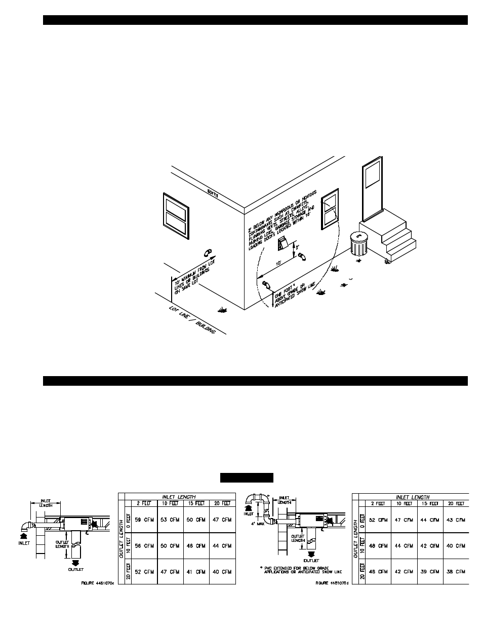
INTAKE ELBOW TERMINATION CLEARANCES
The IN-FORCER has been Listed in accordance with the 1990 BOCA national Mechanical Codes M-306.1 and M-306.1.1 as follows,
(See Diagram B).
M-306.1 LOCATION: Outside air exhaust and intake openings shall be located a minimum of 10 feet (3048mm) from lot lines or build-
ings on the same lot. When openings front on a street or public way, the distance shall be measured to the centerline of the street or
public way.
M-306.1.1 INTAKE OPENINGS: Outside air intake openings shall be located a minimum of 10 feet (3048mm) from any hazard or
noxious contaminant such as vents, chimneys, plumbing vents, streets, alleys, parking lots and loading docks. When a source conta-
minant is located within 10 feet (3048mm) of an intake opening, such opening shall be located a minimum of 2 feet (610mm) below
the contaminant source.
IN ADDITION TO THESE CODES THE MANUFACTURER RECOMMENDS THAT:
• The intake elbow should be a minimum of 1 foot above grade or anticipated snow line.
DETERMINING CFM CAPABILITIES
Reference the chart of the correct model selecting either the PAI-1T or PAI-2T. The readings for CFM are determined with various
inlet and outlet pipe lengths. The charts are read the same way except the right hand chart takes into consideration an intake elbow
that is extended up to 4’ above exterior penetration for below grade applications or to extend above anticipated snow line. The top
row of the chart has inlet 3” diameter PVC pipe lengths from 2 to 20 feet. The left hand column has outlet 6” diameter pipe lengths
from 0 to 20 feet. Pipe lengths must be calculated in equivalent feet, (See Diagram H, Page 6). With correct model selected, deter-
mine pipe lengths and read intersection of inlet and outlet pipe lengths to determine CFM. Consult Tjernlund Products for information
on CFM data with pipe runs longer than those indicated on the charts.
MODEL PAI-1T
TABLE 2
*
IF TERMINATING BELOW GRADE
OR ANTICIPATED SNOW LINE,
USE EXTENSION PROCEDURE AS
SHOWN IN TABLE 2 OR TABLE 3.
If possible, terminate the IN-FORCER on a wall that does not face the direction of prevailing
winds. This will diminish the possibility of wind induced damper fluctuation noise.
DIAGRAM B