Tjernlund PAI-2T Fresh Air In-Forcer (Discontinued) 8504039 Rev A 06/00 User Manual
Page 6
INSTALLATION (TOOLS REQUIRED)
• 3-1/2” hole saw or reciprocating saw
• 5/16”, 1/4” nut runner or socket
• Drill and 1/2” bit
• Blade screwdriver
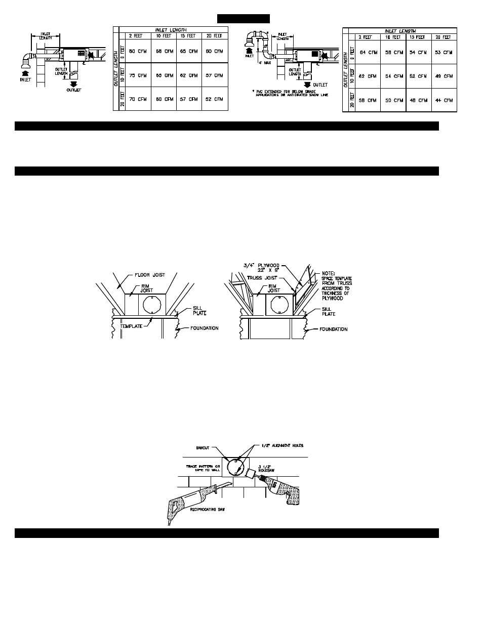
CUTTING PVC OPENING THROUGH WALL
Note:
Before cutting opening through wall, consider layout of PVC pipe runs and confirm intake elbow termination clearances are
met as shown on page 4.
1. A) Attach template to the rim joist in between the floor joists ensuring that it is snug against the subfloor and joist that IN-FORCER
will be mounted to, (See Diagram B). If unit is to be installed on floor trusses, the template should be adjusted to compensate
for the thickness of the added plywood as described in truss mounting section below, (See Diagram C).
B) If IN-FORCER is not being installed between floor joists or trusses, attach the template to the wall it will be exiting, ensuring
IN-FORCER will be level.
2. Using 1/2” bit, drill pilot holes noted on the template from inside through rim joist, wall board, siding, etc., keeping drill bit
perpendicular to the wall. 1/2” bit must be long enough to penetrate through exterior.
3. Remove template from rim joist and attach to building exterior, aligning pilot hole markings on template with holes previously
created in Step #2.
4. Using 3-1/2” hole saw or a reciprocating saw and appropriate blade, cut opening through rim joist, wall board, siding, etc., following
the template outline for the pipe, (See Diagram D).
5. Knock out material exposing hole through the wall.
TRUSS MOUNTING
If IN-FORCER will be mounted on a floor truss instead of a joist follow this section, otherwise, skip to installation of IN-FORCER.
1. Cut a piece of plywood measuring 22” x 9”.
2. Position 22” side of plywood flush against sub floor.
3. Secure plywood to trusses with a minimum of 4-8 penny nails or 1-1/2” wood screws.
5
DIAGRAM B
DIAGRAM C
DIAGRAM D
TABLE 3
MODEL PAI-2T
FLOOR JOIST
FLOOR TRUSS