Tjernlund UC1 Universal Control (Version X.02 or Earlier) 8504107 Rev 08/02 User Manual
Page 7
6
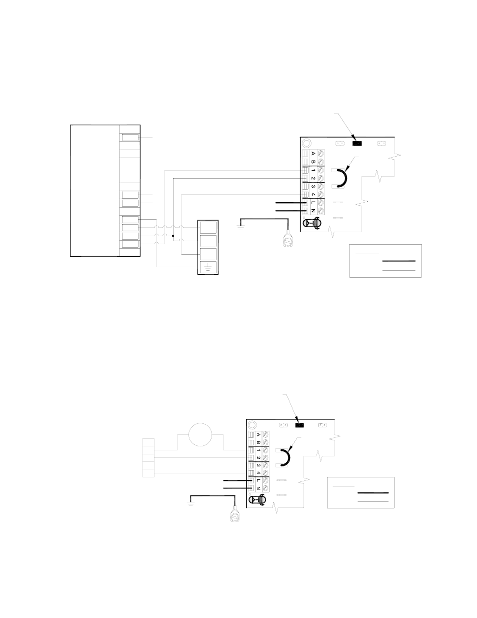
UC1 UNIVERSAL CONTROL CONNECTED WITH A SINGLE ZONE 24 VAC THERMOSTAT
XN
R
U
N
IVER
SAL C
O
N
T
R
O
LLER
THERMOSTAT
G
G
INTERNAL CONTROL
OF FURNACE
W
C
Y
R
R
Y
AS APPLIANCE INTERLOCK VOLTAGE.
RED JUMPER POSITION MUST BE THE SAME
XL
J1
J2
W
DRY
115V
24V
IMPORTANT:
D/N 9183046-5
115 VAC
24 VAC
LEGEND:
CALL
JUMPER
50/60 Hz
SUPPLY
115 VAC
SPADE TERMINAL IN ELECTRICAL BOX.
GROUND
CRIMP GROUND WIRE TO GROUNDING
IMPORTANT:
1. Connect W from t-stat to #1 on terminal block of UC1.
2. Connect #2 on UC1 terminal block to C on internal control terminal strip of furnace/boiler.
3. Connect #4 on UC1 terminal block to W on internal control terminal strip of furnace/boiler.
4. Make sure RED voltage jumper on UC1 is on 24V.
5. Connect 115 VAC supply voltage to L & N terminals on UC1. Crimp Ground wire to grounding spade terminal in UC1.
Important: Installer must supply overload and disconnect protection.
6. If not previously completed, connect ground from UC1 whip to Venter ground. Connect Black and White leads from UC1 whip
to Venter motor leads. Connect Blue and Yellow leads from UC1 whip to Fan Prover switch. Prover Leads are not polarity sensitive.
UC1 UNIVERSAL CONTROL CONNECTED WITH A 24 VAC ELECTRONIC IGNITION MODULE
XN
R
UNIV
E
RS
A
L CO
NTRO
LLE
R
D/N 9183046-8
115 VAC
24 VAC
LEGEND:
HONEYWELL IGNITION
CONTROL
MV
MV
PV
CALL
AS APPLIANCE INTERLOCK VOLTAGE.
RED JUMPER POSITION MUST BE THE SAME
XL
J1
J2
DRY
115V
24V
PV
MV / PV (2)
MV (1)
PV (3)
BNR GND (4)
24V GND (5)
24V (6)
(7)
(8)
SPARK (9)
OR
PI
YE
GR
YE
WH
OR
YE
WH
OR
GR
GAS VALVE
JUMPER
50/60 Hz
SUPPLY
115 VAC
SPADE TERMINAL IN ELECTRICAL BOX.
GROUND
CRIMP GROUND WIRE TO GROUNDING
IMPORTANT:
1. Remove the wire on MV at gas valve and connect it on #1 on UC1 terminal block.
2. Connect #2 on UC1 terminal block to MV/PV.
3. Connect #4 on UC1 terminal block to MV on gas valve.
4. Make sure RED voltage jumper on UC1 is on 24V.
5. Connect 115 VAC supply voltage to L & N terminals on UC1. Crimp Ground wire to grounding spade terminal in UC1.
Important: Installer must supply overload and disconnect protection.
6. If not previously completed, connect ground from UC1 whip to Venter ground. Connect Black and White leads from UC1 whip
to Venter motor leads. Connect Blue and Yellow leads from UC1 whip to Fan Prover switch. Prover Leads are not polarity sensitive.
To interlock more than two 24/115 VAC heaters, add the MAC4E for a total of up to 5 heaters. It is powered by and communicates
with the UC1 through a factory wired whip.
To interlock a millivolt water heater and a 24/115 VAC furnace or boiler, add the WHKE and MAC1E.
MILLIVOLT INSTALLATIONS
Each millivolt appliance interlocked with the UC1 must have its own WHKE kit installed. The WHKE Gas Pressure Switch actuates
the Venter through the A - B Dry contacts. The Linear Limit switch disables the heater in the event of a venting malfunction.
IMPORTANT: Each millivolt appliance interlocked with the UC1 must have its own Linear Limit spill switch.