Fan prover venter uc1 – Tjernlund UC1 Universal Control (Version X.02 or Earlier) 8504107 Rev 08/02 User Manual
Page 5
UC1 INSTALLATION
Do not mount the UC1 junction box on a heat source that exceeds 140oF (60oC). Examples of improper mounting surfaces
include vent pipe, top of heater casing or any place where radiant or convective heat would cause the junction box temperature to
exceed 140oF.
The UC1 is intended for indoor installation only.
Using the key hole slots on the back of the UC1 junction box as a template, mark 4 holes on the mounting surface, drill pilot holes
if necessary, and secure junction box using provided screws.
The UC1 has a 2 foot whip that contains a ground lead and the leads to power the Venter motor and connect to the Fan Prover. If
it is desirable to mount the UC1 more than 2 feet from the Fan Proving Switch an additional electrical junction box and appropriate
length of conduit will be necessary. Any added wire should be 14 gage and a pig tail should be added to each ground wire con-
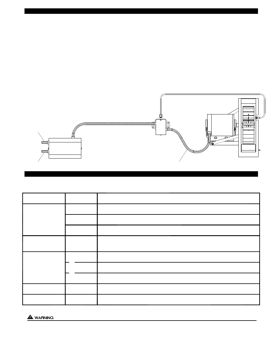
nection so that each electrical junction box is grounded. See diagram below for a typical UC1, Fan Prover and Venter installation.
TYPICAL UC1, FAN PROVER AND VENTER INSTALLATION
ELECTRICAL WIRING
ELECTRICAL SPECIFICATIONS
All wiring from the UC1 to the appliance must be appropriate Class 1 wiring as follows: installed in rigid metal conduit, intermediate
metal conduit, rigid non-metallic conduit, electrical metallic tubing, Type MI Cable, Type MC Cable, or be otherwise suitably protected
from physical damage.
4
POWER
REQUIREMENTS
EXTERNAL
POWER SWITCHING
CAPACITY
J1 / J2
JUMPER
SAFETY
CIRCUIT
ADD VENTER MOTOR
LOAD PLUS 1/2 AMP
FOR UC1 LOAD
EXTERNAL
CALL TRIGGER
METHODS
J1 / J2
P1 / P2
L / N
3 TO 4
T-BLOCK
T-BLOCK
(RELAY K1)
XL / XN
UC1 CONTROL
M & MTR
(RELAY K2)
T-BLOCK
A / B
24V
1 / 2
115V
1 / 2
OR
OR
USED TO JUMP CALL HOT (24 VAC) OR CALL LINE (115 VAC) FROM TERMINAL 1 TO TERMINAL 3.
CONNECTED TO FAN PROVER.
1 mA @ 5 VDC. DO NOT SUPPLY POWER HERE.
REMOVE J1-J2 JUMPER IF A DIFFERENT VOLTAGE SOURCE IS PROVIDED TO TERMINAL 3.
120 VAC ±10 %, 50/60 Hz
MOTOR - 1 H.P. MAX. @ 120 VAC, 50/60 Hz
USER-PROVIDED 24 VAC AT TERMINALS 1 & 2. 1 = CALL HOT, 2 = COMMON. CONTROL
REQUIRES 5 mA @ 24 VAC TO TRIGGER. MOVE RED VOLTAGE JUMPER TO "24V" LOCATION.
3 mA @ 5 VDC. MOVE RED VOLTAGE JUMPER TO "DRY" LOCATION. DO NOT SUPPLY POWER.
USER-PROVIDED CONTACT CLOSURE FROM A TO B. SIZE CONTACT CLOSURE TO HANDLE
GENERAL PURPOSE - 15A @ 120 VAC, 50/60 Hz
DURING OPERATION THE CONTROL USES 50 mA MAX @ 120 VAC
MOTOR - 1 H.P. MAX. @ 120 VAC, 50/60 Hz
150 mA MAX @ 120 VAC, 50/60 Hz
CAN ONLY BE CONNECTED TO TJERNLUND-SPECIFIED AUXILIARY DEVICE
CIRCUIT PROTECTION PROVIDED BY INSTALLER
GENERAL PURPOSE - 15A @ 120 VAC, 50/60 Hz
RESISTIVE - 10A @ 28 VDC PILOT DUTY - 470 VA
USER-PROVIDED 115 VAC AT TERMINALS 1 & 2. 1 = CALL LINE, 2 = NEUTRAL. CONTROL
REQUIRES 1 mA @ 115 VAC TO TRIGGER. MOVE RED VOLTAGE JUMPER TO "115V" LOCATION.
D/N 9183006H
FAN PROVER
VENTER
UC1
ALUMINUM SENSING TUBE, 4 FT. MAXIMUM LENGTH
2 FT. MAXIMUM LENGTH UNLESS ADDITIONAL
CONDUIT AND J-BOX ARE ADDED
INSTALLER-SUPPLIED CONDUIT
AND 3 WIRE, MINIMUM 14 GAGE
INSTALLER-SUPPLIED
115 VAC CONNECTION
BURNER INTERLOCK
CONNECTION
INSTALLER-SUPPLIED