Tjernlund UC1 Universal Control (Version X.02 or Earlier) 8504107 Rev 08/02 User Manual
Page 4
LED INDICATOR LIGHT STATUS & FAULTS
LED #4 & #5 Flashing Alternately
= Prover start up fault. Venter Prover contacts “Closed” across P1 & P2 upon appliance call
before Venter is turned on. Prover status check must be activated, see page 3.
LED #4 & #5 Flashing in Unison
= Fan Prover circuit is “Open” longer than 60 seconds on start-up or 10 seconds during run
cycle. Venter Prover contacts are not staying “Closed” across P1 & P2 safety circuit.
LED #4 Flashing & #5 on Continuous = System in Pre-Purge. (Pre-Purge options 0, 15, 30, 60 seconds)
LED #5 Flashing & #4 on Continuous = System in Post-Purge. (Post-Purge options 0, 30 seconds or 1, 2, 4, 8, 16 minutes)
IMPORTANT: To reset faults, verify fault by checking the LEDs and then remove call for heat.
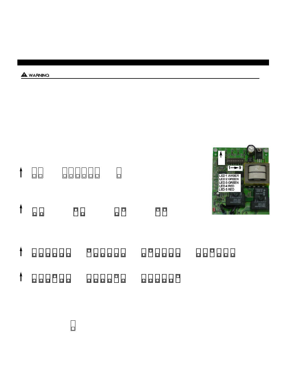
PRE / POST PURGE AND PROVER STATUS CHECK DIP SWITCH SETTINGS
Remove power to Venter and heating equipment when installing, servicing or changing dip switch settings. Failure to do so may result in
personal injury and/or equipment damage. LED #5 (RED) should not be on if 115 VAC supply power is removed from the control.
Pre-purge
Used for a Venter with longer vent runs to get draft fully established throughout the vent system prior to burner ignition. Also bene-
ficial for negative pressure prone environments. IMPORTANT: Pre-purge settings must be shorter than primary control lockout
time unless wired prior to primary control (i.e. aquastat / thermostat).
Post-purge
A Venter post-purge has been factory set at 2 minutes. Confirm that dip switch #5 is in the up or "on" position. Oil fired equipment
requires that the post-purge be long enough to eliminate post cycle nozzle drip odor. A longer post-purge may be necessary for
longer vent runs or high heat retention, refractory lined combustion chambers. A shorter post-purge may be desired for gas installations
or when using the UC1 to control a combustion air In-Forcer.
3
Pre-Purge
Post-Purge
Prover Status
Check Activated
DIP SWITCH NUMBERING
1
ON
ON
ON
PRE-PURGE SETTINGS
POST-PURGE SETTINGS
P1 & P2 FAN PROVER SAFETY CIRCUIT “OPEN” UPON APPLIANCE CALL
The Prover Status Check is activated from the factory. When activated the UC1 Universal Control
checks across P1 & P2 safety circuit (Fan Prover) to verify that the Fan Prover switch is “Open”
upon a call for heat and not stuck “Closed”. IMPORTANT: This must always be in the down
“Activated” position when side wall venting. When using the PS1505 Fan Prover in conjunc-
tion with a draft inducer on a vertical termination stack, “natural draft” may be sufficient to keep
Prover contacts closed prior to a call for heat by an interlocked appliance. This is the only condi-
tion where this safety feature should be deactivated. Push up or “ON” to deactivate.
Prover Status
Check Activated
2
3
4
5 6
7 8
9
9
1 2
1 2
1 2
1 2
0 Seconds
15 Seconds
30 Seconds
60 Seconds
PRE-PURGE SETTINGS
4
3
4
8
6
5
7
3
5 6 7 8
3 4 5 6 7 8
3
7
5
4
6
8
4
3
4
8
6
5
7
3
5 6 7 8
3 4 5 6 7 8
4 Minutes
8 Minutes
16 Minutes
1 Minute
0 Seconds
30 Seconds
2 Minutes
POST-PURGE SETTINGS
ON
ON