Tjernlund UC1 Universal Control (Version X.02 or Earlier) 8504107 Rev 08/02 User Manual
Page 6
SEQUENCE OF OPERATION WITH UC1 UNIVERSAL CONTROL:
Control signal from thermostat, aquastat, primary control or gas valve is intercepted and routed to terminal “1” on UC1 terminal
strip. When terminal “1” is energized with either 24 VAC or 120 VAC, the Venter motor is energized. After draft is established, the
Fan Proving Switch closes within 5 to 10 seconds energizing terminal “4”, which completes the circuit allowing burner to fire.
NOTE: If a Venter pre-purge is selected, the burner will not fire until the pre-purge time is finished. The Venter will continue to run
after the burner has finished firing for the set post-purge time cycle. The UC1 is set for a 2 minute post-purge time period from the
factory. See “Pre / Post-Purge Settings” on page 3 for details.
The "1" input terminal on the UC1 can accept either a 24 VAC or 120 VAC control signal. IMPORTANT: The RED jumper
must be positioned based on appliance interlock voltage. For most furnace applications it may be easier to interlock with the 24
VAC thermostat circuit. For most boiler applications it may be easiest to interlock with the 120 VAC aquastat or primary control cir-
cuit to the burner motor. Choose the interlock method that best fits your application. If using the “DRY” contact activation method,
use terminals A & B on UC1 control and position the RED voltage jumper tab in the “DRY” position. See millivolt appliance inter-
lock diagram for further information.
The steps listed under each diagram are intended as a supplement to the diagram. Wiring colors or designations may vary by
manufacturer. If you are unable to wire the UC1 as outlined in these instructions, call Tjernlund’s Customer Service Department
toll free at 1-800-255-4208 for assistance.
IMPORTANT: To reset faults, verify fault by checking the LEDs and then remove call for heat.
VENTER GROUND, MOTOR AND PROVER SAFETY CIRCUIT CONNECTIONS
VENTER PROVER CONNECTIONS
Blue and Yellow leads from UC1whip (P1 and P2) safety circuit must be connected to a Fan Prover switch. Leads are not polarity
sensitive.
C1 UNIVERSAL
VENTER MOTOR CONNECTIONS
Connect Black and White motor leads from UC1 whip to Venter motor leads. Venter motor must not exceed 1 h.p. Make sure
venter motor is wired for proper rotation. Consult motor nameplate for rotation.
VENTER GROUND CONNECTION
Connect Green ground lead from UC1 whip to Fan Prover ground screw along with ground from Venter motor.
MULTIPLE APPLIANCE INTERLOCKS
To interlock with one additional 24/115 VAC heater add the MAC1E. It is a stripped down auxiliary board version of the UC1 and
is powered by and communicates with the UC1 through a factory wired whip.
5
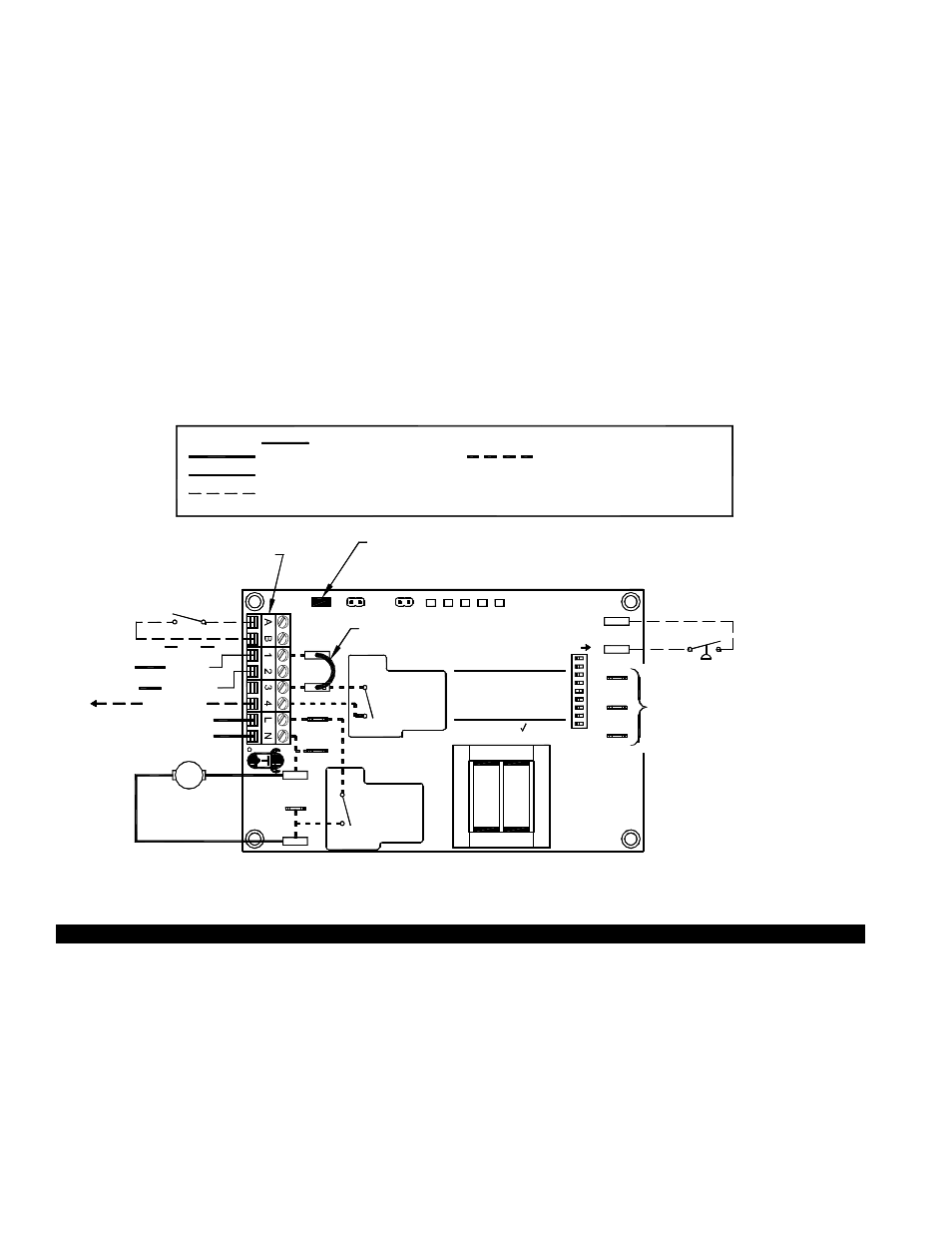
IMPORTANT:
RED JUMPER POSITION MUST BE THE SAME
AS APPLIANCE INTERLOCK VOLTAGE.
CALL
RELAY
INTERLOCK
COMMON
NEUTRAL
PRODUCTS,
INC.
MOTOR
1 H.P. MAX @ 115 VAC
SUPPLY
115 VAC
50/60 Hz
R
TJERNLUND
9183006
NO
MTR
M
MOTOR
RELAY
N
COM
NO
115 VAC
24 VAC
D/N 1303958-1
DO NOT SUPPLY VOLTAGE
TO "A" OR "B".
DO NOT SUPPLY POWER!
5 VDC BOARD-GENERATED POWER
HOT
24 VAC
USER-PROVIDED
CALL SWITCH
LINE
OR
"DRY"
OR
115V
J2
COM
24V
DRY
LEGEND:
115 VAC
5
POST-PURGE SETTINGS
FOR TJERNLUND
TO P1, P2, C, GND
AUXILIARY
OR F. DOING SO
WILL DAMAGE THE
CONNECT POWER
OPEN PROVER OPTION
(9)
(3 - 8)
9
7
8
6
CONTROL.
DEVICES. DO NOT
F
GND
ON
LED1
PRE-PURGE SETTINGS
LED5 LED4
LED2
LED3
(1 - 2)
2
4
3
1
C
P1
P2
PROVER
J1
XL
XN
115 OR 24 VAC FROM CALL JUMPER
OR USER-PROVIDED VOLTAGE
FROM TERMINAL 3 TO 4 WITH CALL
JUMPER REMOVED
K2
K1
APPROVED
MAC1E OR MAC4E
JUMPER
RED
RED
GREEN
GREEN
AMBER
WARNING: Disconnect power supply from the UC1 and heating equipment when making wiring connections and servicing the
Venter. Failure to do so may result in personal injury and/or equipment damage. LED #5 (RED) should be off with
power removed.
UC1 UNIVERSAL CONTROL WIRING SCHEMATIC
The Ground lead, Venter motor and Fan Prover leads are factory connected to the UC1 circuit board. Venter Ground, motor and
Fan Prover wiring connections are made at the free end of the 2 foot whip.