Tjernlund UCRT Rooftop Inducer Universal Control (Version X.06) 8504162 Rev 01/10 User Manual
Page 7
6
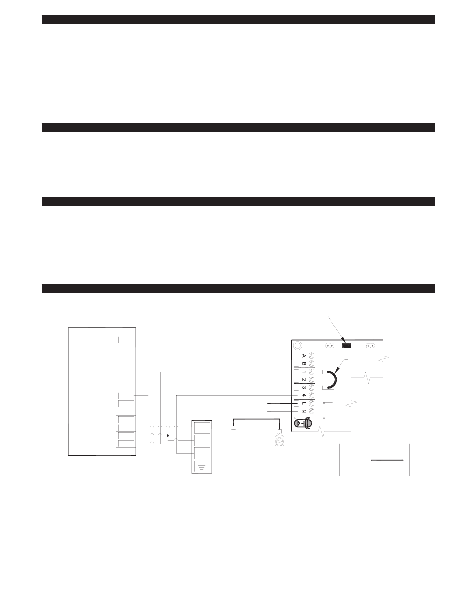
UC1 UNIVERSAL CONTROL CONNECTED WITH A 24 VAC ELECTRONIC IGNITION MODULE
XN
R
UNIV
E
RS
A
L
CO
NTRO
LLE
R
D/N 9183046-8
115 VAC
24 VAC
LEGEND:
HONEYWELL IGNITION
CONTROL
MV
MV
PV
CALL
AS APPLIANCE INTERLOCK VOLTAGE.
RED JUMPER POSITION MUST BE THE SAME
XL
J1
J2
DRY
115V
24V
PV
MV / PV (2)
MV (1)
PV (3)
BNR GND (4)
24V GND (5)
24V (6)
(7)
(8)
SPARK (9)
OR
PI
YE
GR
YE
WH
OR
YE
WH
OR
GR
GAS VALVE
JUMPER
50/60 Hz
SUPPLY
115 VAC
SPADE TERMINAL IN ELECTRICAL BOX.
GROUND
CRIMP GROUND WIRE TO GROUNDING
IMPORTANT:
1. Remove the wire on MV at gas valve and connect it on #1 on UC1 terminal block.
2. Connect #2 on UC1 terminal block to MV/PV.
3. Connect #4 on UC1 terminal block to MV on gas valve.
4. Make sure RED voltage jumper on UC1 is on 24V.
5. Connect 115 VAC supply voltage to L & N terminals on UC1. Connect the 2 green ground wires in UCRT to supply ground.
Important: Installer must supply overload and disconnect protection.
6. If not previously completed, connect Black, White and Red leads from UCRT to like colors in Rooftop Inducer whip 4x4 weather-
proof junction box. Connect the Green/Yellow ground lead in UCRT to the ground screw in the Rooftop Inducer whip 4x4
weatherproof box. Connect Blue and Yellow leads from UCRT to PSA-1 Fan Prover switch. Prover Leads are not polarity sensitive.
INDUCER GROUND, MOTOR AND PROVER SAFETY CIRCUIT CONNECTIONS
ROOFTOP INDUCER PSA-1 FAN PROVER CONNECTIONS
The Blue and Yellow leads from UC1 (P1 and P2) safety circuit must be connected to the PSA-1 Fan Prover switch. Leads are not
polarity sensitive. When venting only millivolt appliances, the PSA-1 Fan Prover is not needed. See WHKE instructions or consult
factory.
1 U
NIVERSAL
ROOFTOP INDUCER MOTOR AND COOLING FAN CONNECTIONS
Connect Black, White and Red leads from UCRT to like colors in Rooftop Inducer whip 4x4 weatherproof junction box.
UCRT / ROOFTOP INDUCER GROUND CONNECTIONS
Connect the two Green ground leads within the UCRT to the ground of the power supply service panel. Connect the
Green/Yellow stripe lead to the Green ground screw within the Rooftop Inducer whip 4x4 weatherproof junction box.
MULTIPLE APPLIANCE INTERLOCKS
To interlock with one additional 24/115 VAC heater add the MAC1E. It is a stripped down auxiliary board version of the UC1 and
is powered by and communicates with the UC1 through a factory wired whip.
To interlock more than two 24/115 VAC heaters, add the MAC4E for a total of up to 5 heaters. It is powered by and communicates
with the UC1 through a factory wired whip. Consult factory for installations with more than 5 heaters.
To interlock a millivolt water heater and a 24/115 VAC furnace or boiler, add the WHKE and MAC1E.
MILLIVOLT HEATER INSTALLATIONS
Each millivolt appliance interlocked with the UC1 must have its own WHKE kit installed. The WHKE Gas Pressure Switch actuates
the Inducer through the A - B Dry contacts. The Linear Limit switch disables the heater in the event of a venting malfunction.
IMPORTANT: Each millivolt appliance interlocked with the UC1 must have its own Linear Limit spill switch.
MULTIPLE MILLIVOLT HEATER INSTALLATIONS
Multiple millivolt heaters can be installed by using the A-B dry contact terminals of the UC1, MAC1E or MAC4E. Wire each WHKE
gas pressure switch in parallel across A-B terminals of UC1, MAC1E or MAC4E. Wire Linear Limit safety switch into each individ-
ual millivolt heater. For further information consult factory or WHKE instructions.
UC1 BURNER INTERLOCK WIRING DIAGRAMS