Tjernlund UCRT Rooftop Inducer Universal Control (Version X.06) 8504162 Rev 01/10 User Manual
Page 13
5. Activate burner(s) at full capacity. Gradually adjust balancing baffle(s) or speed control to maintain a slight negative draft
(-0.02" to -0.05" W.C. or -5 to -12.5 Pa) at the heater’s draft sampling location(s). Allow vent temperatures to reach steady
state by referencing breaching flue gas temperatures.
6 Once flue gas temperatures have stabilized, verify that balancing baffle(s) or speed control are adjusted so that a slight nega-
tive draft (-0.02" to -0.05" W.C or -5 to -12.5 PA) is measured at draft sampling location(s). Individual appliance vent connec-
tions may require balancing baffles to evenly regulate draft.
7. Adjust balancing baffle(s) or speed control so that a slight positive draft (neutral to +0.01" W.C. or +2.5 Pa) is measured at the
appliance draft sampling location. Flue gases should just start to spill from the draft hood/draft diverter or barometric draft control.
8. Turn the PSA-1 Fan Prover Switch adjustment screw clockwise in 1/6-turn increments, waiting 2-3 seconds after each adjust
ment until the pressure switch opens and no continuity is read. Shut off heater for 5 minutes while continuing to allow Inducer
to operate.
9. Fire heater and readjust the balancing baffle(s) or speed control so that a negative draft (-0.02 to -0.05" W.C. or -5 to -12.5 Pa )
is once again measured at the appliance draft sampling location. This readjustment must be enough to cause the PSA-1 Fan
Prover Switch to close. The PSA-1 may take a few moments to close after each adjustment.
10. Confirm Fan Prover Switch set point by adjusting balancing baffle(s) or speed control so that a slight positive draft (neutral to
+0.01" W.C. or +2.5 Pa) is measured at the appliance draft sampling location. Flue gases should just start to spill from the
draft hood/draft diverter or barometric draft control and the Fan Prover Switch should open. Readjust the balancing baffle(s) or
speed control so that a negative draft (-0.02 to -0.05" W.C. or -5 to -12.5 Pa) is once again measured at the appliance draft
sampling location. Verify that the PSA-1 Fan Prover Switch closes.
11. IMPORTANT: Reconnect PSA-1 Fan Prover leads to switch that were jumpered together in Step # 3. Run entire heating/vent
system through 3 cycles to verify proper burner light off and operation. Verify that each appliance lights off properly with all
other appliances not firing. If barometric draft control(s) are excessively open, adjust weight so the
draft control damper opens less and repeat process starting with Step # 3.
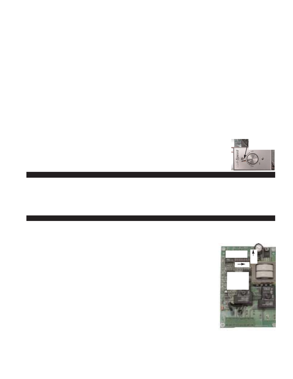
12. Use a permanent marker or sticker to make a mark on speed control faceplate where final adjustment
was, (See Diagram B).
13. Sign and date these instructions to verify that the PSA-1 Fan Prover interlock was completed.
These instructions must remain on site. SIGN:_____________________ DATE :___________
COMBUSTION AIR
Adequate combustion air is vital for proper combustion and for safe venting. Likewise, for proper Inducer performance, adequate
combustion air must be available to the appliance. Many installers assume adequate combustion air is present, especially in older
structures. In some cases this is a false assumption, because many structures have been made "tight" due to weatherization. Size
the combustion air opening(s) into the equipment room as outlined in NFPA 31, 54 & 211. Tjernlund’s IN-FORCER
TM
combustion
air intake systems provide a convenient, automated way to supply combustion air to the equipment room. When installing the
Rooftop Inducer it is not necessary to supply any more combustion air than normally required when conventional venting.
UC1 UNIVERSAL CONTROL OPERATIONAL CHECK
1. Confirm power is supplied to the Control. LED #6 (RED) should be on.
2. Activate the UC1 by initiating an appliance call for heat. LED #1 (AMBER) should be on.
3. The motor relay will close and activate the Inducer motor. LED #3 (GREEN) should be on.
4. If the safety circuit across P1 & P2 (Inducer Prover) is closed, indicating an approved condition,
the appliance interlock relay will close making terminal #3 closed to terminal #4 & LED #2
(BLUE). Appliance burner should fire.
5. Remove power to the UC1 and any interlocked appliances. The LED #6 (RED) or any LED’s
should not be on. Test the safety circuit by removing the Blue or Yellow Lead from PSA-1 Fan
Proving Switch. Do not let the opened Lead touch a ground or damage may occur to the control
when power is Reestablished. Reestablish power to the UC1 and interlocked appliances and ini-
tiate a call for heat. After 60 seconds a Prover Start Up fault should arise with LED #4 flashing 3 times.
6. Remove appliance call for heat and power to the UC1 and any interlocked appliances. The LED
#6 (RED) or any LED’s should not be on. Reconnect Blue or Yellow Fan Prover lead to PSA-1
Fan Proving Switch terminal removed from in step 5.
7. Reestablish power to UC1 and interlocked appliances and initiate a call for heat to confirm proper
operation of UC1 and appliance.
RESETTING FAULT CODE CREATED BY STEP 5 OF OPERATIONAL CHECK
IMPORTANT: Prior to accessing the fault code memory, note the settings of the dip switches so
that they can be returned to their original Pre / Post-Purge positions. When power is supplied to the
UC1 use caution when moving dip switches.
The last fault code can be retrieved at any time by setting all dip switches 1-8 to the up, or “on” position. The last fault code, or
lack there of, will be indicated by counting the number of times LED 4 flashes. By moving any of the dip switches back to their
original position, the fault code will be cleared. NOTE: The UC1 board must have its 115 VAC power supply present when any of
the (1-8) dip switches are moved back to their original position for the fault code to clear.
12
1 9
LED 1 AMBER
LED 2 BLUE
LED 3 GREEN
LED 4 RED
LED 5 RED
LED 6 RED
POWER LED
ON
DIAGRAM B
PLACE A MARK ON
SPEED CONTROL
FINAL SETTING