Tjernlund UCRT Rooftop Inducer Universal Control (Version X.06) 8504162 Rev 01/10 User Manual
Page 10
9
Alarm
A
Violet
0.3 A, AC
OIL VALVE
R
A
Blue
Orange
F
F
White
T
Black
Red/White
T
115 VAC
BURNER MOTOR
IGNITION TRANS
500 VA
10 FLA / 60 LRA
Line Voltage Thermostat
60 Hz
SUPPLY
J2
UNI
V
E
R
S
A
L
CO
NT
RO
LLE
R
XN
XL
J1
RED JUMPER POSITION MUST BE THE SAME
AS APPLIANCE INTERLOCK VOLTAGE.
IMPORTANT:
115V
DRY
24V
D/N 9183046-3
115 VAC
LEGEND:
CALL
JUMPER
Limit
or Aquastat Control
Low Voltage
Jumper
50/60 Hz
SUPPLY
115 VAC
SPADE TERMINAL IN ELECTRICAL BOX.
GROUND
CRIMP GROUND WIRE TO GROUNDING
IMPORTANT:
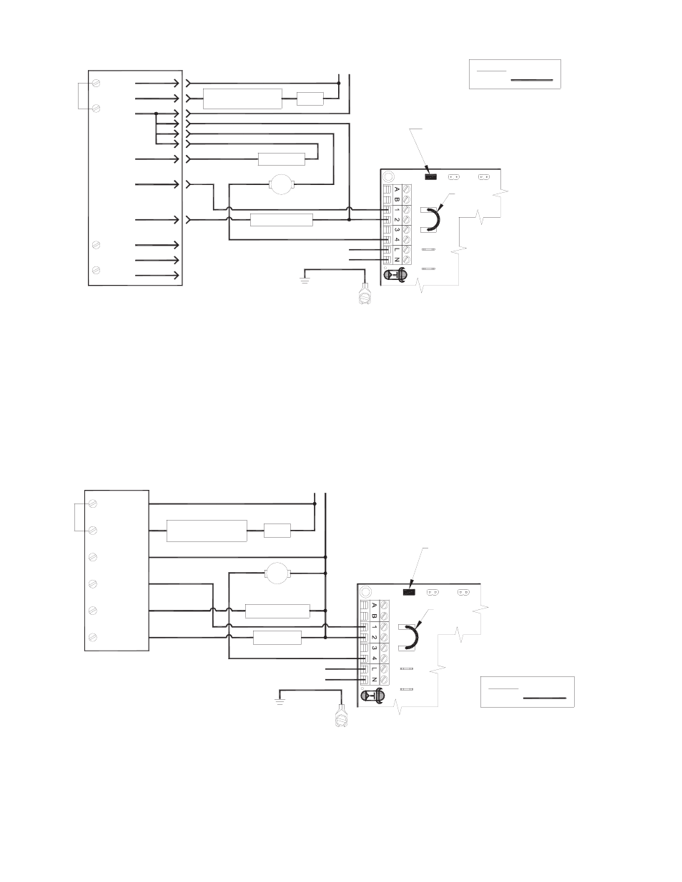
1. Disconnect burner motor wire off the Orange on Carlin and connect burner motor terminal Orange of Carlin to #1 on UC1 terminal block.
2. Connect #2 on UC1 terminal block to L2 or N
3. Connect #4 on UC1 terminal block to burner motor wire removed from Orange of Carlin.
4. Make sure RED voltage jumper on UC1 is on 115V.
5. Connect 115 VAC supply voltage to L & N terminals on UC1. Connect the 2 green ground wires in UCRT to supply ground.
Important: Installer must supply overload and disconnect protection.
6. If not previously completed, connect Black, White and Red leads from UCRT to like colors in Rooftop Inducer whip 4x4 weather-
proof junction box. Connect the Green/Yellow ground lead in UCRT to the ground screw in the Rooftop Inducer whip 4x4
weatherproof box. Connect Blue and Yellow leads from UCRT to PSA-1 Fan Prover switch. Prover Leads are not polarity sensitive.
UC1 UNIVERSAL CONTROL CONNECTED TO A HONEYWELL R7184 SERIES OR EQUIVALENT
PRIMARY CONTROL WITH A LINE VOLTAGE THERMOSTAT OR AQUASTAT
Burner
Alarm
Cad Cell
A
Interrupted
Intermittant
Motor
A
IGNITION TRANS
BURNER MOTOR
R
Oil Valve
Limit
R7184
L1
T
T
L2
OIL VALVE
115 VAC
60 Hz
SUPPLY
Limit
24
V
DRY
1
15V
XL
UNIVERSAL
CONT
ROL
L
E
R
XN
J1
J2
RED JUMPER POSITION MUST BE THE SAME
AS APPLIANCE INTERLOCK VOLTAGE.
IMPORTANT:
D/N 9183046-6
115 VAC
LEGEND:
CALL
JUMPER
Ignitor
Line Voltage Thermostat
or Aquastat Control
Low Voltage
Jumper
50/60 Hz
SUPPLY
115 VAC
SPADE TERMINAL IN ELECTRICAL BOX.
GROUND
CRIMP GROUND WIRE TO GROUNDING
IMPORTANT:
1. Disconnect burner motor wire off the R7184 and connect burner motor terminal of R7184 to #1 on UC1 terminal block.
2. Connect #2 on UC1 terminal block to L2 or N.
3. Connect #4 on UC1 terminal block to burner motor wire removed from R7184.
4. Make sure RED voltage jumper on UC1 is on 115V.
5. Connect 115 VAC supply voltage to L & N terminals on UC1. Connect the 2 green ground wires in UCRT to supply ground.
Important: Installer must supply overload and disconnect protection.
6. If not previously completed, connect Black, White and Red leads from UCRT to like colors in Rooftop Inducer whip 4x4 weather-
proof junction box. Connect the Green/Yellow ground lead in UCRT to the ground screw in the Rooftop Inducer whip 4x4
weatherproof box. Connect Blue and Yellow leads from UCRT to PSA-1 Fan Prover switch. Prover Leads are not polarity sensitive.
UC1 UNIVERSAL CONTROL CONNECTED WITH A CARLIN 40200, 42230, 48245, 50200, 60200
SERIES OR EQUIVALENT AND A LINE VOLTAGE THERMOSTAT OR AQUASTAT