Diagram a – Tjernlund UCRT Rooftop Inducer Universal Control (Version X.06) 8504162 Rev 01/10 User Manual
Page 12
11
PSA-1 FAN PROVING SWITCH ADJUSTMENT
NOTE: This section is also repeated in the Rooftop Inducer instruction manual.
1. Drill an appliance draft sampling hole in the vent riser after each
draft diverter or between the flue outlet and the draft hood /
barometric draft control of each appliance. For most oil burners
sample over-fire draft. Connect draft gauge to sampling hole,
(See Diagram A).
2. For installations with a barometric draft control: Adjust weight on
draft control to minimum or most responsive position (Less Draft).
3. WARNING: This step requires that the wires connected to
the PSA-1 Fan Prover terminals be temporarily removed
and jumpered together. Disconnect power before proceeding.
Remove power source and connect leads attached to the C (common)
and N/O (normally open) terminals of the PSA-1 together. Attach a
continuity tester to the C and N/O terminals of the PSA-1 Switch. Turn
the PSA-1 adjustment screw counter clockwise until it seats against
the stop. The PSA-1 must be reconnected to the interlocked
heaters(s) per the appropriate wiring diagram after completing
these procedures. Failure to do so may result in a hazardous condition such as an explosion, fire or carbon monoxide
poisoning resulting in property damage, personal injury or death. The UC1 interlock control number 9 dip switch should be
up or “ON” so the Pre-Cycle Prover Status check is deactivated.
Close all access doors and openings to the mechanical room that would typically be closed during heating equipment operation.
Fire all other heating equipment not connected to this vent system and operate exhaust fans or air consuming devices within the
facility that could affect the air pressure of the mechanical room.
4. Activate Rooftop Inducer and adjust balancing baffle(s) or speed control so that (-0.08" W.C. or -20 Pa) is read at the appliance
draft sampling position(s) referenced in Step 1. The PSA-1 switch contacts should close. If switch contacts do not close move
pressure sampling probe closer to the Inducer. Do not move sampling probe between manual damper and Inducer inlet.
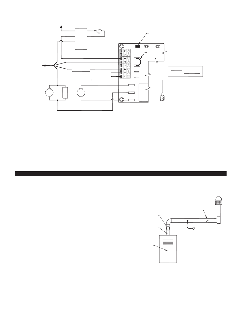
UC1 UNIVERSAL CONTROL CONNECTED WITH A HONEYWELL R8184 SERIES
OR EQUIVALENT PRIMARY CONTROL AND A BURNER MOTOR POST-PURGE
RED JUMPER POSITION MUST BE THE SAME
AS APPLIANCE INTERLOCK VOLTAGE.
U
N
IVER
SAL
C
O
N
T
R
O
L
XN
BURNER
NM
T
R
M
THERMOSTAT
OIL VALVE
W
O
WHITE
ORANGE
B
F
F
T
T
IMPORTANT:
XL
J1
J2
115V
DRY
24V
115 VAC
LEGEND:
CALL
JUMPER
BLACK
HONEYWELL R8184
SERIES OR EQUIVALENT
VENTER
MOTOR
MOTOR
IGNITION
TRANS
50/60 Hz
SUPPLY
115 VAC
SPADE TERMINAL IN ELECTRICAL BOX.
GROUND
CRIMP GROUND WIRE TO GROUNDING
IMPORTANT:
D/N 9183047-4 10/16/03
L1 OR B1
CONNECT TO
CONNECT TO
L2 OR B2
1. Separate the burner motor wire and ignition transformer from the Orange wire of R8184.
2. Connect the Orange of R8184 to #1 on UC1 terminal block.
3. Connect #2 on UC1 terminal block to White on R8184 and L2 or B2.
4. Connect the HOT wire of oil solenoid valve to #4 on UC1 terminal block and neutral wire to White or N.
5. Connect burner motor and ignition transformer HOT wires to M terminal on UC1 and neutrals to White or N.
6. Make sure RED voltage jumper on UC1 is on 115V.
7. Connect 115 VAC supply voltage to L & N terminals on UC1. Connect the 2 green ground wires in UCRT to supply ground.
Important: Installer must supply overload and disconnect protection.
8. If not previously completed, connect Black, White and Red leads from UCRT to like colors in Rooftop Inducer whip 4x4 weather
proof junction box. Connect the Green/Yellow ground lead in UCRT to the ground screw in the Rooftop Inducer whip 4x4
weatherproof box. Connect Blue and Yellow leads from UCRT to PSA-1 Fan Prover switch. Prover Leads are not polarity sensitive.
FIGURE 8052070
TJERNLUND ROOFTOP
DRAFT INDUCER
(MUST BE MOUNTED
SIX FEET OF SENSING
VERTICALLY WITHIN
FAN PROVING SWITCH
LOCATION)
APPLIANCE
GAS APPLIANCE DRAFT
SAMPLE LOCATION
FLAME RETENTION
OIL BURNERS
OVER-FIRE DRAFT
DRAFT CONTROL
/ DRAFT HOOD
TJERNLUND ABD-SERIES
BALANCING BAFFLE
(IF BAFFLE IS INSTALLED
IT MUST BE POSITIONED
AFTER FAN PROVING SWITCH)
DIAGRAM A