Tjernlund UCRT Rooftop Inducer Universal Control (Version X.06) 8504162 Rev 01/10 User Manual
Page 11
10
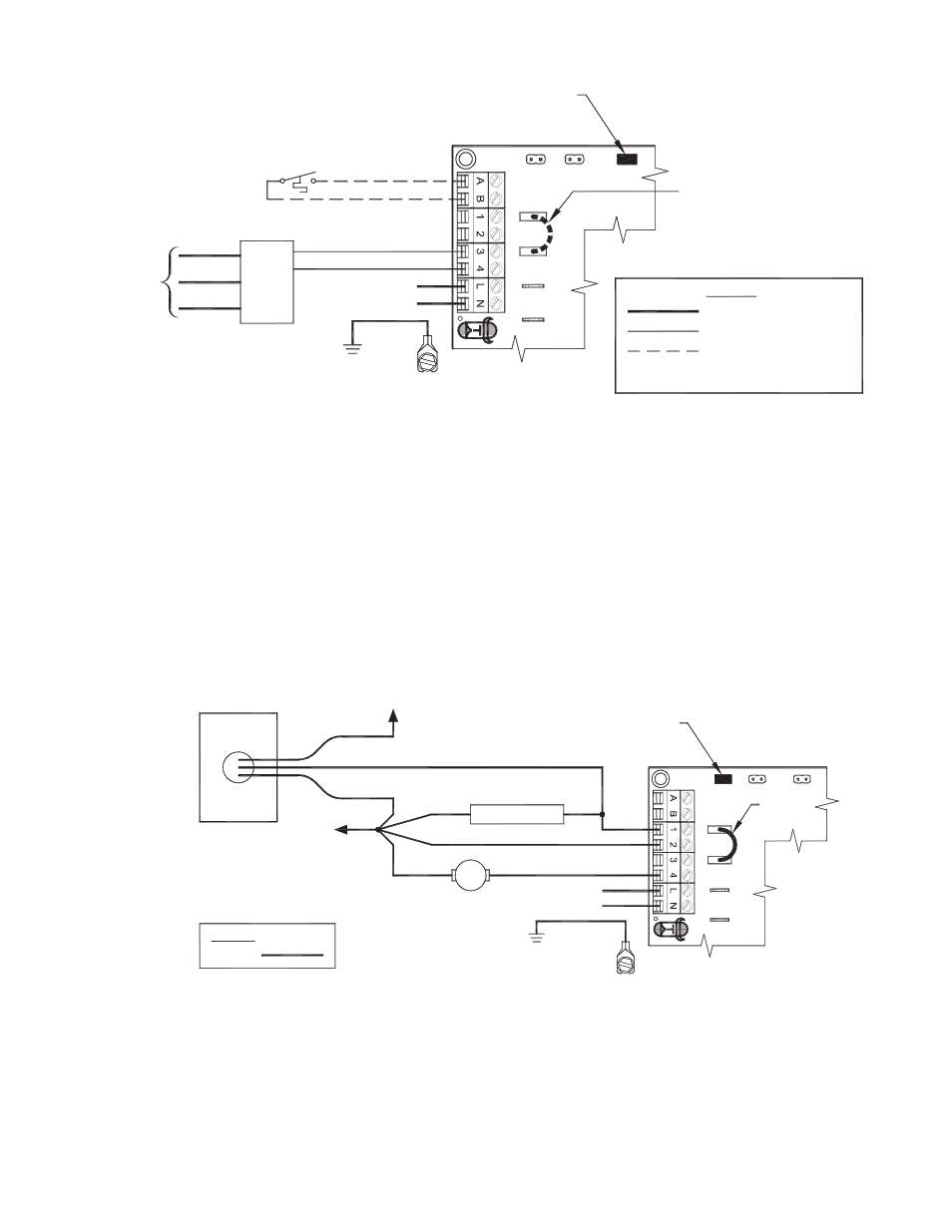
UC1 UNIVERSAL CONTROL CONNECTED TO AN OIL-FIRED FURNACE WITH A
HONEYWELL T87 OR EQUIVALENT NON-POWERED THERMOSTAT
XN
R
UNIV
E
RS
A
L
CO
NTRO
LLE
R
REMOVE JUMPER TO AVOID
AS APPLIANCE INTERLOCK VOLTAGE.
RED JUMPER POSITION MUST BE THE SAME
XL
J1
J2
DRY
115V
24V
IMPORTANT:
BACKFEEDS OR SHORT
50/60 Hz
SUPPLY
115 VAC
NON-POWERED THERMOSTAT
F
F
T
T
PRIMARY CONTROL
SPADE TERMINAL IN ELECTRICAL BOX
GROUND
CRIMP GROUND WIRE TO GROUNDING
IMPORTANT:
OR EQUIVALENT
5 VDC BOARD-GENERATED
LEGEND:
115 VAC
DO NOT SUPPLY POWER!
POWER.
LOW VAC
HONEYWELL T87 OR EQUIVALENT
W
O
WHITE
ORANGE
B
BLACK
HONEYWELL
R8184 SERIES
IMPORTANT:
FACTORY-
WIRED
CIRCUITS.
1. IMPORTANT: Remove J1 & J2 Call Jumper on UC1 to avoid backfeeds or short circuits.
2. Connect T87 or Equivalent non-powered thermostat to A and B terminals on UC1.
3. Remove T T Jumper from R8184 or equivalent Primary Control.
4. Connect #3 on UC1 terminal block to T terminal of Primary Control.
5. Connect #4 on UC1 terminal block to remaining T terminal of Primary Control.
6. Make sure RED voltage jumper on UC1 is on DRY.
7. Connect 115 VAC supply voltage to L & N terminals on UC1. Connect the 2 green ground wires in UCRT to supply ground.
Important: Installer must supply overload and disconnect protection.
8. If not previously completed, connect Black, White and Red leads from UCRT to like colors in Rooftop Inducer whip 4x4 weather-
proof junction box. Connect the Green/Yellow ground lead in UCRT to the ground screw in the Rooftop Inducer whip 4x4
weatherproof box. Connect Blue and Yellow leads from UCRT to PSA-1 Fan Prover switch. Prover Leads are not polarity sensitive.
NOTE: If burner safety control goes out on lockout, the Inducer will continue to run as long as a call for heat is present.
UC1 UNIVERSAL CONTROL CONNECTED TO A HONEYWELL
R8184 SERIES OR EQUIVALENT PRIMARY CONTROL
50/60 Hz
R
WHITE
ORANGE
BLACK
HONEYWELL
R8184 SERIES
OR EQUIVALENT
IGNITION TRANS
BURNER MOTOR
WHITE
SUPPLY
115 VAC
BLACK
UNIV
E
RS
A
L
CONT
ROLLE
R
XN
RED JUMPER POSITION MUST BE THE SAME
IMPORTANT:
AS APPLIANCE INTERLOCK VOLTAGE.
J1
XL
J2
115V
DRY
24V
115 VAC
LEGEND:
CALL
JUMPER
SPADE TERMINAL IN ELECTRICAL BOX.
GROUND
CRIMP GROUND WIRE TO GROUNDING
IMPORTANT:
D/N 9183046-2 10/16/03
L1 OR B1
CONNECT TO
CONNECT TO
L2 OR B2
WHITE
1. Separate the Black burner motor wire from the Orange wire of R8184 Primary Control.
NOTE: Do not separate the ignition transformer wire from the Orange.
2. Connect Orange wire of R8184 to #1 on UC1 terminal block.
3. Connect #2 on UC1 terminal block to White on R8184 and L2 or B2.
4. Connect Black of burner motor to #4 on UC1 terminal block.
5. Make sure RED voltage jumper on UC1 is on 115V.
6. Connect 115 VAC supply voltage to L & N terminals on UC1. Connect the 2 green ground wires in UCRT to supply ground.
Important: Installer must supply overload and disconnect protection.
7. If not previously completed, connect Black, White and Red leads from UCRT to like colors in Rooftop Inducer whip 4x4 weather-
proof junction box. Connect the Green/Yellow ground lead in UCRT to the ground screw in the Rooftop Inducer whip 4x4
weatherproof box. Connect Blue and Yellow leads from UCRT to PSA-1 Fan Prover switch. Prover Leads are not polarity sensitive.