Cop uc1 – Tjernlund DCOP1 Constant Operating Pressure Draft Control 8504174 (Discontinued) User Manual
Page 7
6
The DCOP1 must be installed by a qualified installer (an
individual properly licensed and/or trained) in accordance
with all local codes or, in their absence, in accordance with
the appropriate National Fire Protection Association #31,
#54, #211 and the National Electrical Code.
All wiring from the DCOP1 to the appliance(s) must be appro-
priate Class 1 wiring as follows: installed in rigid metal con-
duit, intermediate metal conduit, rigid non-metallic conduit,
electrical metallic tubing, Type MI Cable, Type MC Cable, or
be otherwise suitably protected from physical damage
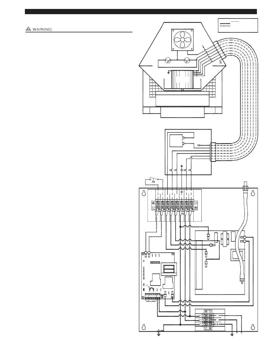
COP CONTROL POWER CONNECTIONS
Connect 115 VAC supply voltage to L & N terminals and
Ground wire to ground on COP control terminal block.
Important: Installer must supply overload and disconnect
protection.
INDUCER MOTOR & COOLING FAN CONNECTIONS
NOTE: The maximum distance wire can be ran from the
RT-Series Inducer 4 x 4 Junction box to the DCOP1 control
is 250 feet.
Cut Orange motor capacitor wire in RT-Series Inducer pro-
vided 4 x 4 Junction box and cap end with a wire nut that
previously went to RT-Series Inducer motor.
Connect the Orange Motor Capacitor lead to the MOTOR
ORG location on COP terminal strip.
Connect Red and White/Red motor leads from Rooftop
Inducer whip to MOTOR RED and WHT/RED location on
COP terminal strip.
Connect the Black & White Cooling Fan leads to COOL FAN
WHT and BLK location.
PSA-1 FAN PROVER CONNECTIONS
The UC1 (P1 and P2) safety circuit must be connected to
the PSA-1 Fan Prover Switch. These connections are done
on the PROVER P1(com) and P2 (n.o.) terminals on the
COP terminal strip. Leads are not polarity sensitive. If using
only millivolt appliances, the PSA-1 Fan Prover is not used.
A WHKE millivolt interlock kit which includes a Linear Limit
spillage switch is required.
1
WH
ITE
BL
AC
K
FIGURE 8052077 5-4-11
IN
T
E
R
L
OC
K
OP
T
ION
S
IN
S
T
RUCT
IO
NS
F
O
R
SEE D
C
O
P
1
MOTOR
CAPACITOR
G
R
O
UND
WH
ITE
BL
AC
K
RE
D
BROWN
WH
ITE
/ R
E
D
COOLING FAN
THERMOSTAT
INDUCER
MOTOR
THERMOSTAT
WH
T / R
ED
BL
AC
K
BR
OW
N
OR
AN
GE
BR
OW
N
RE
D
NUT
S
OR
AN
GE
BL
AC
K
RE
D
WH
T / R
ED
WH
ITE
WH
ITE
BLUE
BLUE
BLACK
INCLUDED 4 X 4 BOX
IMPELLER
WI
RE
BLACK
P2
C
F
GND
P1
CA
L
L
24V
DRY
JU
M
PER
J2
A B
RE
L
A
Y
IN
TE
R
L
O
C
K
K2
K1
J1
XL
M
N
XN
2 3 4
N
L
MTR
1
N.O.
COM
ORG
RED
WHT
BLK
1303284
WHT/
GRN
RED
PROVER
MOTOR
COOL FAN
P2
T1
1
P1
T7
N
GR
N
L
WH
T/R
E
D
YEL
OR
G
BL
U
RE
D
WH
T
BL
K
T1
4
BLK
WHT
GRN
L
N
1303285
BL
U
E
Y
E
LLO
W
WH
ITE
BL
K
WHITE
BLK
T9
T6
T14
T11
T7
T10
WHITE / RED
ORG
RED
GROUND
ORANGE
ORANGE
PSA-1
SIDE VIEW
CUTAWAY
N
L1
RT SERIES
COP
UC1
5 VDC BOARD-GENERATED
115 VAC
LEGEND
DO NOT SUPPLY POWER!
POWER SUPPLY
115 VAC
POWER.
4 FT. WHIP
PRE-WIRED
INCLUDED
115V
1
2
3
4
5
AMBER
BLUE
GREEN
RED
RED
6
RED
L.E.D.S
1 THRU 9
DIP SWITCHES
UP = ON
WIRING CONNECTIONS BETWEEN DCOP1 AND ROOFTOP INDUCER