Tjernlund DCOP1 Constant Operating Pressure Draft Control 8504174 (Discontinued) User Manual
Page 17
16
ADJUSTMENT OF DRAFT SET POINT, BALANCING BAFFLE(S) AND BAROMETRIC DRAFT CONTROL(S)
Sample Draft at heater manufacturer’s recommended point. If not specified, drill a small sampling hole in vertical riser midway
between flue outlet and Balancing Baffle. Heaters with draft hoods/diverters typically require a slight negative draft between
-0.02" to -0.03" w.c. Heaters with barometric draft controls typically require a negative draft of between -0.02" to -0.05" w.c.
1. Turn on the disconnect or thermostat for the heater farthest from the Inducer and establish call for heat.
2. Gradually open the Balancing Baffle until the manufacturer’s recommended draft range is achieved and lock in place. Wait a few
minutes for heater flue gas temperature to reach steady state and adjust weight on Barometric Draft Control, if present, so that
the damper is slightly open. Re-adjust Balancing Baffle if necessary to maintain draft in recommended range.
3. Repeat steps 1 and 2 for each heater, one heater at a time, moving towards the Inducer.
4. When all heaters have been adjusted fire heaters randomly to assure proper light off and then all together to verify that at the
heating system’s maximum firing rate proper draft levels are maintained for each heater.
5. Pinch the silicon sampling tube closed near the connection to the PSA-1 Fan Prover switch and remove from switch, keeping
seal tight. This will keep the Inducer operating while allowing the PSA-1 Fan Prover switch to open, disrupting the P1 and P2
UC1 prover safety circuit. After a 10 second delay built into the UC1 Safety circuit the Blue Fan Prover #2 LED should go out
and the burners should be disrupted or will not ignite on a call for heat. Reinstall tubing to the PSA-1 Fan Prover.
FINAL OPERATION AND DRAFT CHECK
The PSA-1 Fan Proving Switch is designed to disable the appliance gas valve(s)
or burner motor(s) upon Inducer failure only! It is not designed and cannot
replace, regular vent system inspection, appliance servicing and combustion
testing.
1. Close all doors and windows of the building. If the appliance is installed in
a utility room or closet, close the entrance door to this room. Close fire-
place dampers.
2. Turn on clothes dryer and all exhaust fans such as range hoods, bathroom
exhausts and whole house fans to maximum speeds. Do not operate a fan
used strictly for Summer exhausting.
3. Following the appliance manufacturer’s instructions, place the appliance in
operation, set thermostat for continuous operation.
4. Verify that Inducer operates first, prior to burner ignition. Watch to make sure burner lights off properly.
GAS
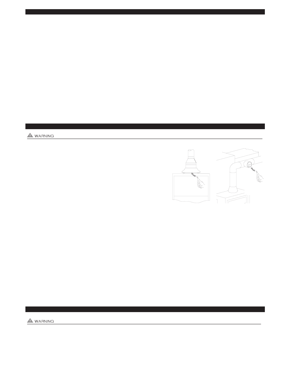
After allowing appliance(s) to operate for 15 minutes, follow the appliance manufacturer’s instructions to verify that the recom-
mended draft is present. In general, most gas appliances will operate safely with flue outlet draft levels from -0.02 to -0.05" W.C..
If the draft is excessive, make necessary adjustments to the balancing baffle, barometric control or DCOP1 draft setting. As a
cross check, a candle or match can be held adjacent to the draft hood or barometric control to verify flame/smoke is being drawn
into, and not rolling out of edge of the relief opening, (See Diagram k). If exhaust gases are escaping from the relief opening of the
draft hood or barometric control, the equipment should not be operated until proper adjustments or repairs are made to provide
adequate draft levels.
OIL
After allowing equipment to operate for 15 minutes, make necessary adjustments to the primary air intake and barometric draft
control to comply with the manufacturer recommended over-fire draft and CO
2
requirements of the burner. In most cases, the
over-fire draft should be in a range of -.02” to -.04” W.C. If adjustments to the primary air intake and barometric draft control do not
provide the required over-fire draft, make necessary adjustments to the balancing baffle or DCOP1 draft setting. Measure over-fire
draft and CO
2
after adjustments.
5. Next, turn on all other fuel-burning appliances within the same room so they will operate at their full input. Repeat Step 3 above,
checking the draft on each appliance.
TROUBLESHOOTING ELECTRICAL PROBLEMS
The following guide is intended to be used if a problem occurs during the use of the Inducer and UC1. It may be necessary to
measure voltage during troubleshooting. Extreme caution must be exercised to prevent injury. If you are unable to determine
the defective part with the use of this guide, call your Tjernlund distributor or Tjernlund Products direct at 1-800-255-4208 for fur-
ther assistance.
PROPER
DRAFT
ESTABLISHED
PROPER
DRAFT
ESTABLISHED
DIAGRAM K