Tjernlund DCOP1 Constant Operating Pressure Draft Control 8504174 (Discontinued) User Manual
Page 6
5
SIZING A COMMON MANIFOLD SERVING MULTIPLE HEATERS
The most important step towards assuring that individual heaters vented into a common manifold draft smoothly is to size the man-
ifold large enough to negate the affects that velocity in the manifold has on the junctions of the heater vent connections.
Exhaust gases moving too quickly in a common vent manifold can amplify the draft at vent connectors by aspirating across the
connector opening and creating an amplified siphon affect. With a properly sized common vent manifold, velocities are maintained
below the point where they have a significant affect on the draft of the individual heater connections.
It is important to note that these sizing recommendations are for the common vent manifold only and that the typically smaller mini-
mum vent diameter listed in the RT-Series Inducer selection table may be used for the remainder of the horizontal vent and chim-
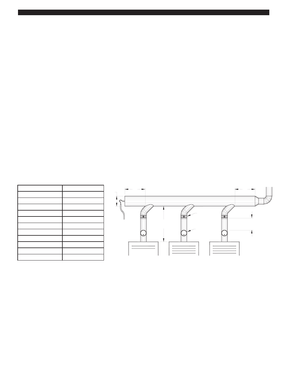
ney. The larger diameter vent common manifold should extend at least 2 diameters beyond the connection point of the last heater
farthest from the Inducer.
1. When in doubt, get help from Tjernlund Tech Service at 800-255-4208, push 0 and ask for technical assistance or
email [email protected] with details of your job.
2. If velocities are known, avoid exceeding 1200 FPM in the vent common manifold.
3. When possible use 45
O
Manifold Tee connections to the common vent manifold in the direction of the Inducer instead of 90
O
Tee connections.
4. Draft hoods/diverters create a disconnect from the heater’s flue outlet greatly buffering sudden changes in draft. Even though
the DCOP1 Constant Pressure Controller reacts quickly to maintain the draft/exhaust set-point, we still recommend installing
single acting barometric draft controls on fan assisted and power burner heaters. The barometric draft controls react instantly to
spikes in vent exhaust volume so that precise draft is always maintained.
5. If possible, locate the larger exhaust volume (i.e. higher BTU/hr. input) vent connections closer to the Inducer. This reduces the
affect of their exhaust on smaller volume connections.
6. The size of the common vent manifold should be at least 90% of the total area of all individual vent connections. See example
below.
Example: A vent layout is required for a job that consists of 4 heating appliances. 1 Appliance has an 8" diameter vent
connector, 2 appliances have 6" diameter vent connectors and 1 appliance has a 4" diameter vent connector.
Add these areas together:
1 x 0.3491 = 0.3491
2 x 0.1964 = 0.3928
1 x 0.0873 = 0.0873
______
0.8292
Total Area = 0.8292 Square Feet x 0.90 (90%) = 0.7463. In looking at the table above, this area is greater than a 10" diameter
pipe but smaller than a 12" diameter pipe. 12" diameter vent is the minimum size the common vent manifold diameter should be. It
is perfectly acceptable to be larger than this area if desired. It is also acceptable to have this area be reduced as the vent system
works backward towards the appliance furthest from the Inducer. In this example, the common vent manifold should extend at
least 24" past the connection point of the appliance farthest from the Inducer.
Breech Size Diameter Area (Square Feet)
3”
0.0491
4”
0.0873
5”
0.1364
6”
0.1964
8”
0.3491
10”
0.5454
12”
0.7854
14”
1.0690
16”
1.3960
18”
1.7670
20”
2.1820
BALANCING
BAROMETRIC
DRAFT CONTROL
(IF PRESENT)
BAFFLE
2D
MINIMUM
COMMON VENT MANIFOLD
MAINTAIN THE FLUE
OUTLET DIAMETER UNTIL
THE COMMON MANIFOLD
INSTALL THE BALANCING BAFFLE
AT LEAST 2 PIPE DIAMETERS ABOVE
THE BAROMETRIC OR FLUE OUTLET
D
2D
HEATER FURTHEST
FROM THE INDUCER
MINIMUM
FAN PROVER
SENSING TUBING TO
DCOP1 AND PSA-1
FIGURE 8054007 4/14/11