Tjernlund DCOP1 Constant Operating Pressure Draft Control 8504174 (Discontinued) User Manual
Page 16
15
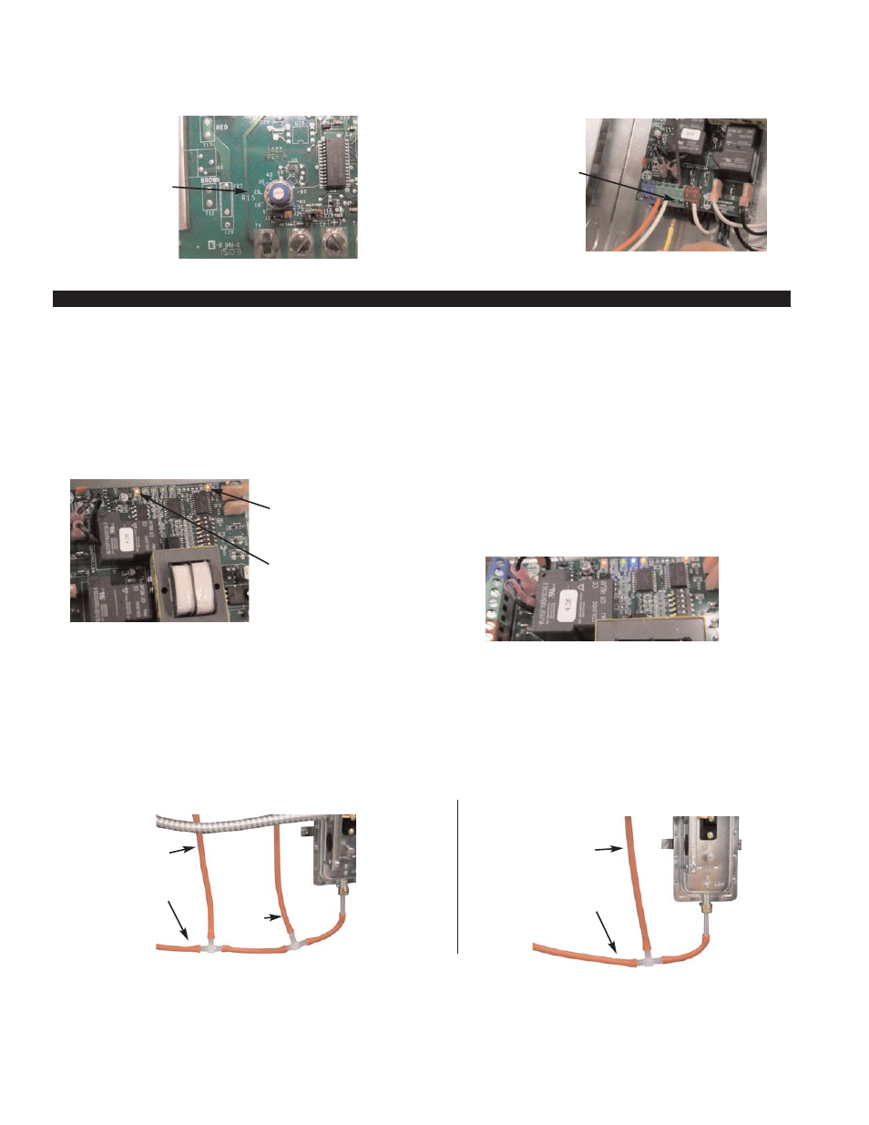
4. Verify that slot on set point adjustment pot for the COP controller is aligned with the "20" hash mark, (See Diagram F).
5. Disconnect the lead(s) connected to terminal #4 of the UC1 circuit board and MAC-Series multiple appliance interlock controls.
This will prevent any interlocked burners from firing, (See Diagram G). On Millivolt appliances turn thermostat off.
VERIFYING SYSTEM OPERATION
With 115 VAC supply power to the L and N of the Draft COP black terminal strip LED #6 should be solid RED and LED #5 on UC1
should be blinking RED. Any interconnected MAC-Series circuit boards should have a solid RED #9 power LED, (See Diagram H).
1. Adjust thermostat of any heater to call for heat. This should cause the following sequence of LED's to light, (See Diagram I).
Amber: Call for heat intercepted
Green: Draft Cop Control and Inducer activated (Green LED is present on UC1 only)
Blue: PSA-1 Prover Switch Closed to allow burner to fire
2. Verify that the Inducer activates by seeing the draft pressure increase (more negative) on your draft gauge as measured with a
tee at draft sensing position at rear end of common manifold or vent connector, (See Diagram J). Gradually adjust the pot on
the COP controller circuit board clockwise. The Inducer should speed up increasing the negative draft pressure. Slowly adjust
the pot on the COP controller counter-clockwise until the draft pressure is maintained at -0.10” w.c.. NOTE: Turning the adjust-
ment pot too far counter-clockwise will cause the Inducer to stall or not be able to start. Readjust clockwise if necessary.
3. Disrupt the call for heat. The Inducer should continue to operate at a consistent negative draft pressure for a the 2 minute post-
purge period (Adjustable from 0 to 16 minutes).
4. Shut off disconnect switch(s) to Heater(s) and re-install the leads removed from the #4 terminal(s) of the UC1 heater interlock
terminal strip. On millivolt appliances turn thermostat back to the on position.
DIAGRAM H
DIAGRAM I
DIAGRAM J
DIAGRAM F
DIAGRAM G
TO DCOP1 JUNCTION
BOX SENSING TUBE
PORT
PSA-1
FAN PROVER
DIAPHRAGM
IN VERTICAL
POSITION
PSA-1
FAN PROVER
DIAPHRAGM
IN VERTICAL
POSITION
TO PRESSURE SENS-
ING TUBE IN VENT
COMMON MANIFOLD
TUBING WITH DRAFT GAUGE REMOVED
TUBING WITH DRAFT GAUGE
TO DCOP1 JUNCTION
BOX SENSING TUBE
PORT
TO
DRAFT
GAUGE
TO PRESSURE SENS-
ING TUBE IN VENT
COMMON MANIFOLD
DCOP1 DRAFT
ADJUSTMENT POT
AND SCALE. CLOCK-
WISE WILL INCREASE
DRAFT.
RED LED #6 INDICATES
115 VAC POWER IS
SUPPLIED TO UC1
BOARD
REMOVE #4 WIRE FROM
UC1, MAC1E OR MAC4E
CONTROL. ON MILLIVOLT
APPLIANCES TURN THER-
MOSTAT OFF.
RED LED #5 FLASHES
EVERY 3 SECONDS WITH-
OUT A CALL FOR HEAT TO
INDICATE UC1 IS WORK-
ING PROPERLY.
LED #1 AMBER - INDICATES CALL FOR HEAT
LED #3 GREEN - DCOP1 AND INDUCER ACTIVATED
LED #2 BLUE - PSA-1 PROVER CLOSED, BURNER FIRES
#3
G
R
N
#2
B
L
U
#1
A
M
B
#6
P
W
R
UC1 BOARD