Tjernlund DCOP1 Constant Operating Pressure Draft Control 8504174 (Discontinued) User Manual
Page 5
4
DCOP1 INSTALLATION
Do not mount the DCOP1 junction box on a heat source that exceeds 140
O
F (60
O
C). Examples of improper mounting surfaces
include vent pipe, top of heater casing or any place where radiant or convective heat would cause the junction box temperature to
exceed 140
O
F (60
O
C). The DCOP1 is intended for indoor installation only.
Using the key hole slots on the back of the DCOP1 junction box as a template, mark 4 holes on the mounting surface, drill pilot
holes if necessary, and secure junction box using provided screws.
ELECTRICAL WIRING
P1 & P2 PRE-CYCLE FAN PROVER STATUS CHECK
Pre-Cycle
Prover Status
Check Deactivated
The Pre-Cycle Prover Status Check is deactivated from the factory. When activated, the UC1
Universal Control checks across P1 & P2 safety circuit (PSA-1 Fan Prover) to verify that the Fan
Prover switch is “Open” upon a call for heat and not stuck “Closed”. Natural draft or winds may be
sufficient to close the PSA-1 Fan Prover switch contacts prior to a call for heat. Keeping the Prover
Status Check activated may cause nuisance lockouts. Push dip switch 9 up or “ON” to deactivate.
9
ON
PRE-PURGE SETTINGS (SEE “PRE-PURGE” ON PAGE 3 PRIOR TO SETTING)
1 2
1 2
1 2
1 2
0 Seconds
5 Seconds
20 Seconds
35 Seconds
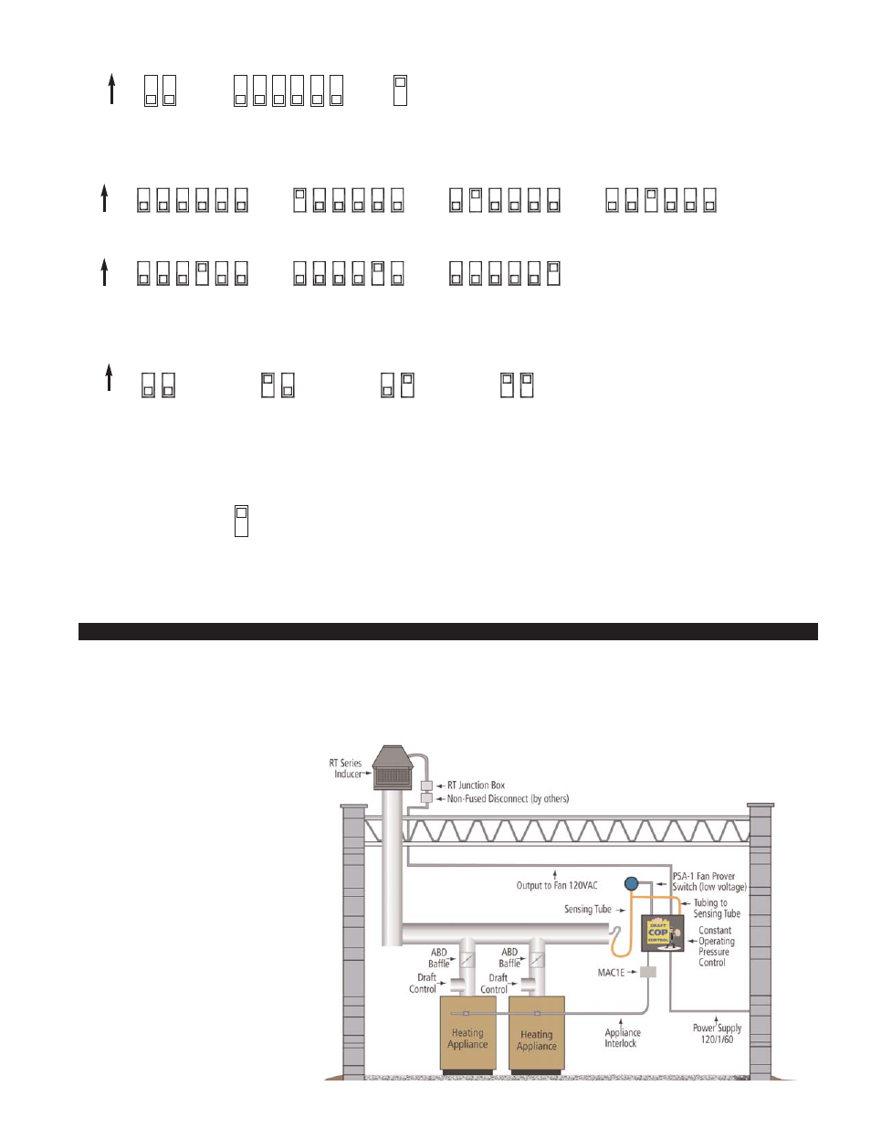
EXAMPLE OF DCOP1
& ROOFTOP INDUCER
INSTALLED WITH
MULTIPLE HEATERS
POST-PURGE SETTINGS (SEE “POST-PURGE” ON PAGE 3 PRIOR TO SETTING)
4
3
4
8
6
5
7
3
5 6 7 8
3 4 5 6 7 8
3
7
5
4
6
8
4
3
4
8
6
5
7
3
5 6 7 8
3 4 5 6 7 8
4 Minutes
8 Minutes
16 Minutes
1 Minute
0 Seconds
30 Seconds
2 Minutes
ON
ON
Pre-Purge
Post-Purge
Pre-Cycle
Prover Status
Check Deactivated
DIP SWITCH NUMBERING
1
ON
2
3 4
5 6
7 8
9