2 junction box to indicator, 3 indicator to peripherals, 4 single-point ground conductor – Rice Lake SURVIVOR PT Series User Manual
Page 20: 5 j-box connections
16
Survivor PT - Pit Type Truck Scale
5.2
Junction Box to Indicator
A 60' section of 6-wire home run cable is supplied. It is to be run in 3/4" galvanized metal conduit from the
junction box to the indicator. A 30" flexible conduit section and watertight conduit connector is provided where
this cable exits the junction box. Galvanized metal conduit must be obtained locally.
Scales over 70 feet in length have two or three j-boxes. Refer to Engineering Drawings provided with scale for
details.
5.3
Indicator to Peripherals
All 3/4" metal conduit for cabling from the indicator to remote displays and other peripheral devices must be
obtained locally. Conduit runs may be buried in a trench or secured above ground. Use separate conduit runs for
AC power and DC data lines to avoid interference. As a general guideline, run AC and DC cables in separate
trenches if possible. When DC data cables must run in the same trench as AC power lines, separate cables as much
as possible.
5.4
Single-Point Ground Conductor
A bare 10-gauge solid wire is run from the scale frame to the grounding lug on the junction box, then underground
to the main AC power earth ground. If the optional DC transient protection board is installed, the ground conductor
should also be connected to the transient protection board’s ground lug. Consult with the local power utility for
restrictions or requirements for utility ground rod connections.
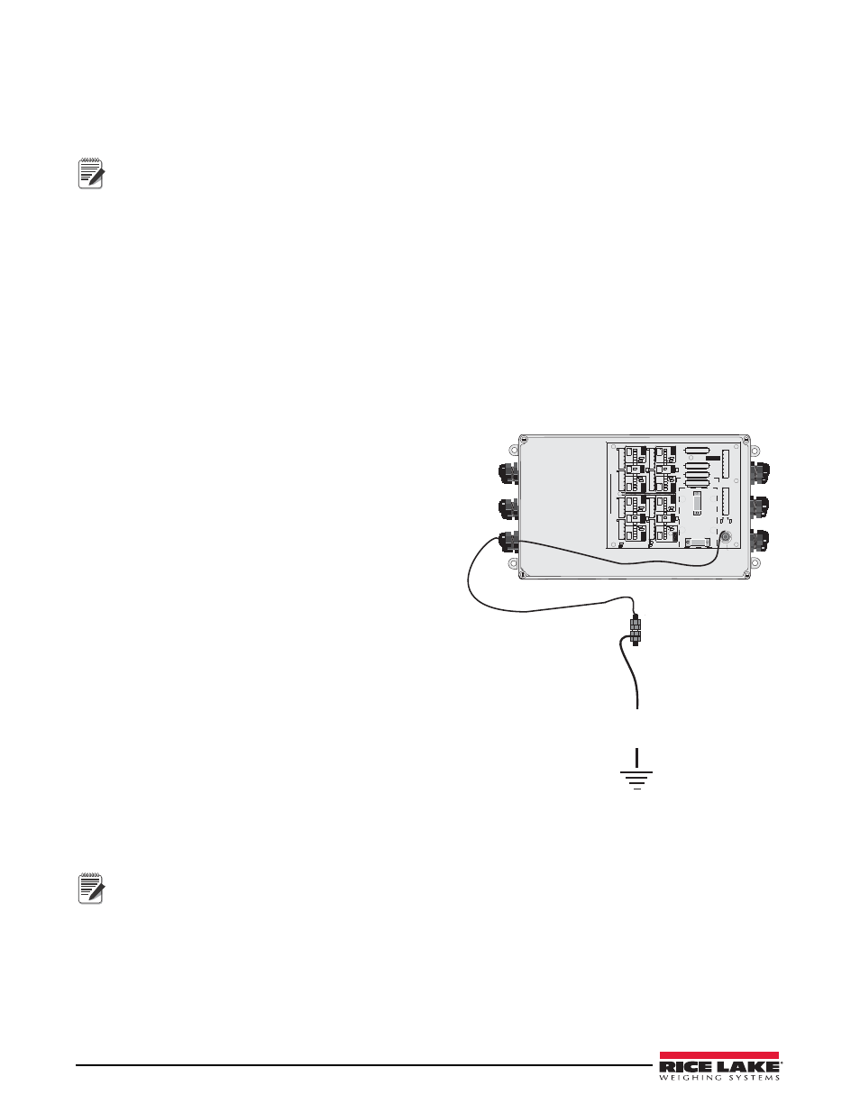
5.5
J-Box Connections
Each JB8SPT j-box is large enough to hold the summing
board, transient protection devices, desiccant package, and
extra load cell cable coiled inside the enclosure.
In a single-platform scale, the single j-box location is
determined by the length of the load cell cables and the four
mounting studs on the outside main beams. Both A and B
modules are equipped with mounting studs. In a multi-axle
scale with independent sections, each section requires its own
junction box to sum the load cell signals from that section.
A summing card mounted within the junction box is used to
make all cable terminal connections. All terminal pin
functions are clearly marked.
A 10-gauge bare ground wire is run from one of the junction
box mounting studs to the ground lug of the junction box as
shown in the figure below. The ground lug on the bottom of
the junction box is connected to a buried ground cable from
the AC power ground terminal or ground rod, thus grounding
the scale frame to the same single-point ground point as the
AC power for the indicator.
Before final closure, add an industrial corrosion inhibitor and
desiccant (RLWS Industrial Corrosion Inhibitor, PN 16037)
to the junction box enclosure. This desiccant protects an enclosure up to 5 ft
3
from internal corrosion for
approximately 1 year.
Make sure that the 10 gauge ground wire makes connection to bare metal.
Note
Ground Lug
(located next to J-box)
R41
JP17
JP7
R52
R50
R40
R24
R14
R15
JP20
JP10
R26
R51
R49
R47
JP16
R45
R43
JP9
R23
R21
JP6
JP8
R17
R38
R36
R34
JP11
R32
R30
R28
R10
R8
JP1
R4
R2
R33
JP12
JP2
VR9
JP19
R48
VR7
JP18
R42
R44
R22
R25
R16
R18
VR2
R19
R39
VR10
R35
R37
VR11
R27
R29
R31
R9
R11
R12
R1
R3
R5
VR5
R6
JP5
JMP/NEG
JMP/POS
VR8
VR3
VR1
VR12
VR6
J1
VR4
J2
R13
R7
EXPANSION/J9
J5
ARC
R46
JP4
JP3
ARGND
JP14
JP15
JP13
L3
L4
L2
J8
J4
J3
J6
L1
R20
J7
INDICATOR/J10
JP
TRIM
TRIM
TO
-EX
+EX
+SI
-EX
+EX
+SI
-EX
+EX
1
+SI
-EX
+EX
+SI
JP
JP
TO
SIGNAL
2005
SIGNAL
CUT
TO
DISABLE
CUT
CELL#
CELL#
CELL#
SHD
1
SHD
-SI
1
-SI
SHD
-SI
1
-SI
SHD
SIGNAL
CUT
TO
CUT
SECT#
DISABLE
CELL#
CELL#
SIGNAL
SIGNAL
SIGNAL
D
L
D
DISABLE
CELL#
SECT#
DISABLE
CELL#
RICE LAKE WEIGHING SYSTEM
S
JP
-EX
+EX
+SI
-EX
+EX
+SI
-EX
+EX
+SI
-EX
+EX
+SI
SIGNAL
TRIM
TRIM
TRIM
TRIM
TRIM
TRIM
Assembly
-EX
-EX
+EX
+SI
SHD
1
SHD
-SI
1
-SI
1
-SI
SHD
1
-SI
SHD
CONNECT BOTH SHUNTS
TO APPLY SIGNAL
SECT#
SIGNAL
SIGNA
L
SIGNAL
CELL#
PN Rev.
+SI
-SI
-SI
SECT#
+SEN
SHD
+SEN
SHD
DISCONNECT BOTH SHUNTS
TO REMOVE SIGNAL
+EX
-SEN
-SEN
CUT TRACE TO ISOLATE SENSE LINE
Transient Board Connectors
Grounding Lug
10 ga. bare ground wire
to DC protection ground
connection before indicator
Figure 5-3. J-Box Grounding.
Note