Rice Lake SURVIVOR LaserLight Series Remote Display - Pole Mount Installation User Manual
Pole mount installation instructions, Laserlight, Remote display
June 2003
78040
LaserLight
™
Remote Display
Pole Mount Installation Instructions
PNs 75850, 75852
This document contains drawings, replacement parts
lists, and instructions for installing the optional pole
mount for the 4" and 6" LaserLight remote displays.
See the
LaserLight
Installation Manual
, PN 75936 for
general installation and configuration and calibration
information.
The LaserLight has no on/off switch.
Before working with the unit, ensure the
power cord is disconnected from the
power outlet.
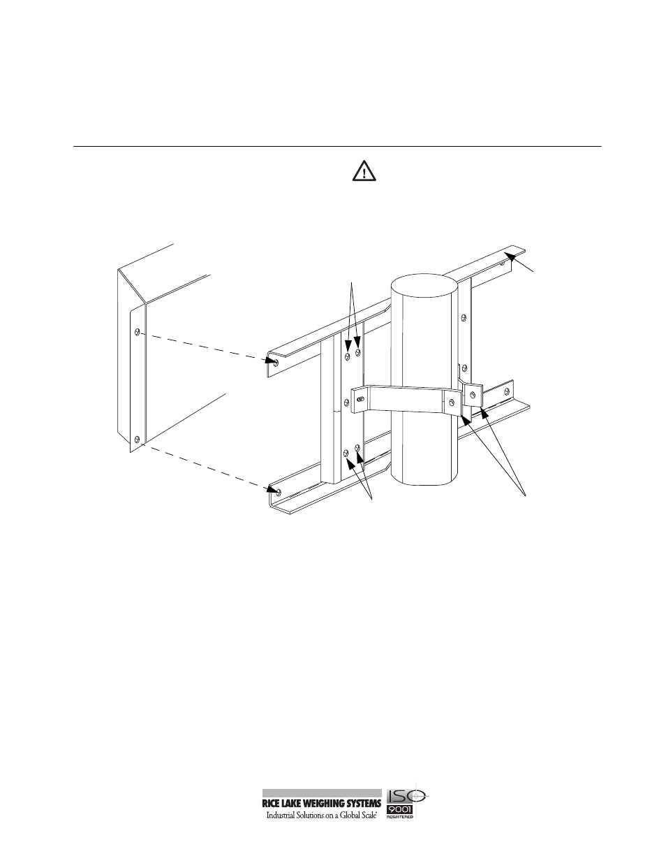
Figure 1. Optional Pole Mount Kit
The LaserLight remote display can be easily mounted to a pole or steel I-beam using the optional pole mounting
weldment and clinching brackets (shown in Figure 1).The pole mounting kit can accomodate either the 4" or the
6" LaserLight. Use the following steps to install the pole option.
1. Use the enclosed 3/8" cap screws, washers, and lock nuts from the parts kit to attach the clinching pole
brackets to the pole mounting weldment. Note that two clinching pole brackets are used for the 4"
models and are attached to the pole mounting weldment using the center holes. Six inch LaserLights
utilize four clinching pole brackets and are connected using the top and bottom hole alignments.
2. Use the enclosed 3/8-16NC bolt (PN 14747) to attach the clinching pole brackets together using washers
and lock nuts. Tighten as necessary.
3. Align the back of the LaserLight remote display to the pole mount weldment so that the holes line up.
4. Use enclosed 1/4" cap screws, washers, and nuts to attach the remote display to the mounting weldment.
Caution
C l i n c h i n g
Pole Brackets
P o l e
M o u n t i n g
Weldment
L a s e r L i g h t
Remote Display
Used for 6"
model
U s e d f o r 6 "
model