Rice Lake SURVIVOR RT Rail Scale User Manual
Page 13
Junction Box and Grounding
9
Be certain each load cell grounding strap is securely connected to the top plate and bottom plate of each load cell
mount. There should be metal-to-metal contact with no presence of paint or grout. This strap is designed to channel
power surges on the deck around—rather than through—the load cell to ground.
Grounding
Strap
Figure 3-2. Grounding strap on load cell mount.
These, and all, ground connections must be torqued to a specified value and retorqued at regular service intervals.
A thick coating of anti-oxidant grease should be maintained on all ground connections to prevent corrosion.
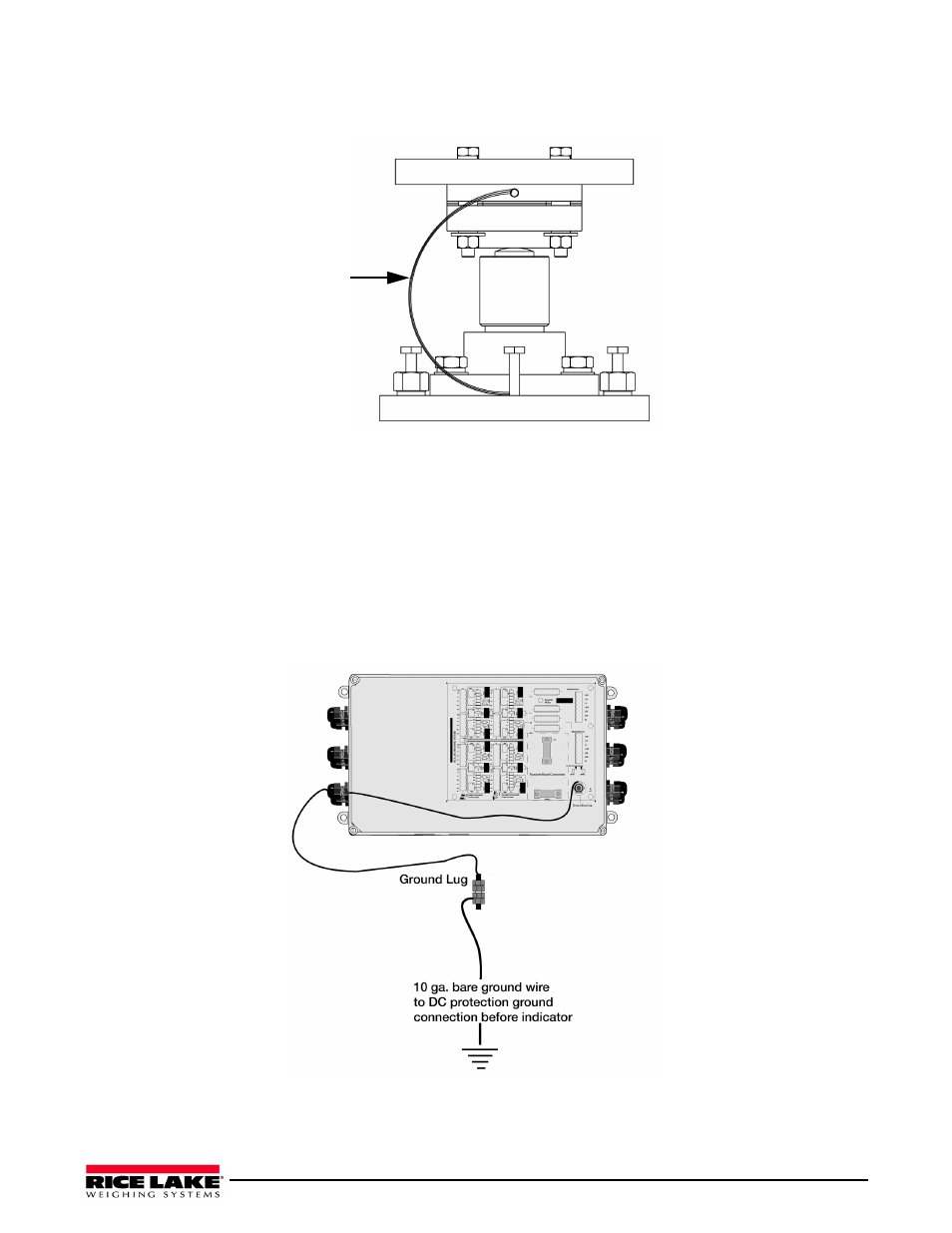
A separate grounding system conductor must extend uninterrupted from the main service panel ground to the scale
to protect load cells and scale wiring from lightning and other transient damage. This ground wire conductor must
be an unsheathed #10 copper wire or larger. Run the bare ground wire conductor intact from the AC power ground
rod to the scale in a separate trench. Bring the wire up from the trench near the junction box and attach it to the
ground lug of the junction box. A #10 bare ground wire is run from the ground lug of the junction box to one of the
junction box mounting studs on the scale frame, thus grounding the scale frame to the same single-point ground as
the AC power for the indicator.
.
ground before indicator
Figure 3-3. Junction box ground wire connections.