Rice Lake Pipe Lever Scale User Manual
Page 7
Assembly Instructions
3
1. Position the four fulcrum stands (Figure 2-1) on the concrete base with gussets facing outward from the
scale. Ensure fulcrum stands are square and level with each other.
Note
If mounting the scale to a frame, ensure the frame is square and all stands are positioned squarely on the
frame.
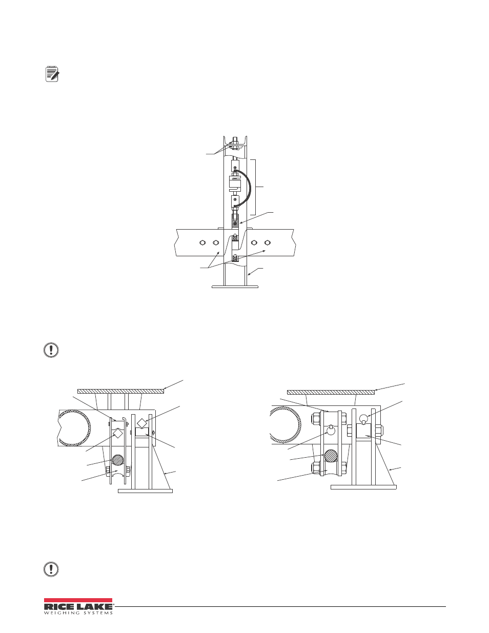
2. Assemble the load cell, ITCM hardware, and center connection shackle to support the nose irons, see
3. Temporarily secure load cell assembly with top and bottom jam nuts on top plate of load cell stand.
Jam Nuts
Center Connection
Shackle
ITCM Hardware
Nose Irons
Load Cell Stand
Figure 2-2. Load Cell Assembly
4. Loosely bolt nose irons to ends of main pipe levers.
5. Set pipe levers in place with outside pivots on bearings of fulcrum stands (see Figure 2-3) with nose irons
supported by center connection shackle in load cell stand.
Grider Chair
Bearing
Fulcrum
Stand Bearing
Outside Pivot
Inside Pivot
Spool
Trunnion Pin
Fulcrum Stand
Type II
Grider Chair
Bearing
Fulcrum
Stand Bearing
Outside Pivot
Inside Pivot
Spool
Trunnion Pin
Fulcrum Stand
Type I
Important
Center load cell stand between main levers. Levers must be level when suspended by the center
connection shackle.
Figure 2-3. Fulcrum Stand Assembly
6. Locate and assemble the loop assembly spool using two bolts and two washers. Position loop assembly
under inside pivot. Attach bearing to two loop side plates using two clevis pins and two cotter pins with
loop bearing resting on inside pivot. Insert trunnion pin.
Important
Bolt heads must face the fulcrum stands.