Rice Lake Load Cells - 441/442 Bridgesensor Load Cell Input to Analog Out User Manual
Page 3
441/442 SPECIFICATIONS
Input/Output Ranges
See table below.
Other switch-selectable ranges possible.
Input Impedance
200k ohm (
Ω
) typical
Output Capability
Voltage:
±
10 VDC, @
±
10 mA
Current: 25 mA DC; 20 V compliance
Zero/Span Controls
Top-accessible, multi-turn, non-interactive
Range:
±
15% of span typical
Excitation Voltage
Switch-selectable, 0-10 VDC in 1 V increments
Fine adjust:
±
5% via multi-turn potentiometer
Excitation Current Capability
120 mA DC @10 VDC excitation; drives up to four 350
Ω
load cells @ 10 VDC
Excitation Stability
±
.01% per
°
C
© 1997 Rice Lake Weighing Systems, Inc. Rice Lake, WI USA. All Rights Reserved
Rice Lake Weighing Systems, Inc., 230 West Coleman Street, Rice Lake, WI 54868
Tel.: (715) 234-9171 Direct Service Hotline: (715) 234-2003 Fax: 715-234-6967
Sense Lead Compensation
Better than 0.01% per 1
Ω
change in leadwire resistance
Leadwire Resistance
10
Ω
max. for 10 VDC excitation/350
Ω
bridge
Response Time
70 mS typical; faster responses available
Common Mode Rejection
100 dB minimum
Isolation
2000 V RMS minimum
Temperature Stability
Better than 0.02% of span per
°
C
Ambient Operating Temperature Range
-10 to +60
°
C
Power
441—115 VAC,
±
10%, 50/60 Hz, 2.5 W max.
441—(Optional) 230 VAC,
±
10%, 50/60 Hz, 2.5 W max.
442—10-30 VDC @ 200 mA typical
Electrical Connection
Inputs
0-5 mV
0-10 mV
0-20 mV
0-25 mV
0-30 mV
0-40 mV
0-50 mV
0-100 mV
0-200 mV
0-250 mV
0-300 mV
0-400 mV
Table of Common Input/Output Ranges
Outputs
Voltage
0-1 V
0-5 V
1-5 V
0-10 V
±
5 V
±
10 V
Current
0-20 mA
4-20 mA
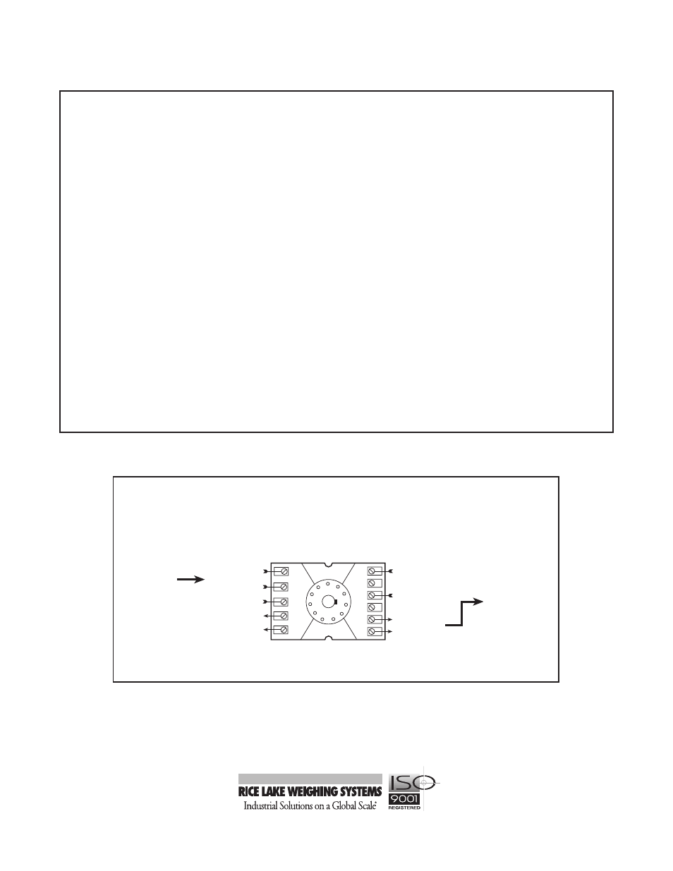
9
3
10
1
11
2
8
4
5
6
7
(+) Output
(–) Signal
(+) AC or DC
(–) AC or DC
Power Input
Output (–)
Excitation (+)
Excitation (+)
Signal (+)
Sense lead (+)
Input (–)
Note: If no sense lead is available, connect pins 6 and 7
Socket
Top View