0 trimming load cell output, 1 trimming individual cells – Rice Lake JB1010 Signal/Excitation Trim User Manual
Page 7
4
5.0 Trimming Load Cell Output
5.1 Trimming Individual Cells
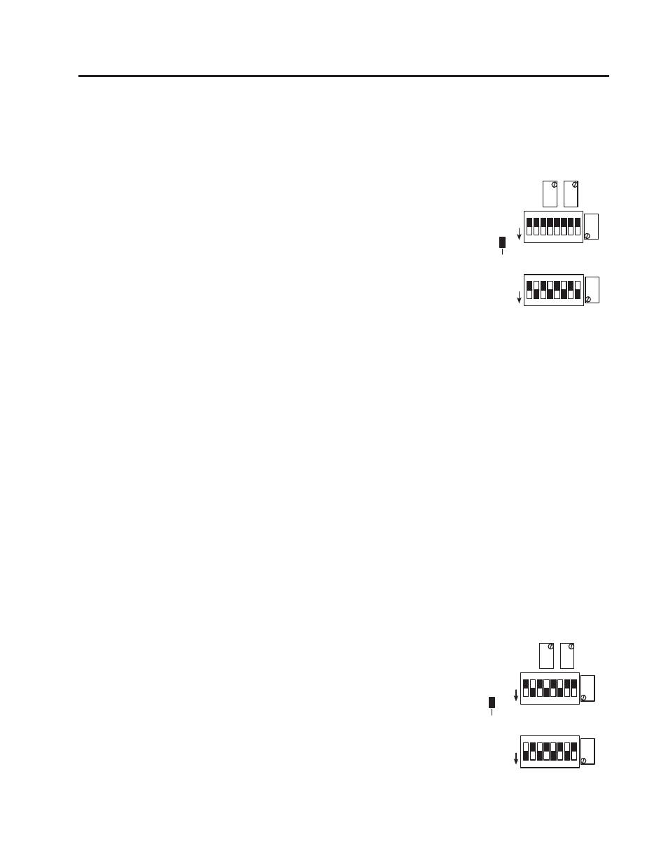
1. Determine what and how you want to trim. If the cells will be trimmed
individually, we recommend a sig nal trim mode. While you can select either
2.5KΩ or 1KΩ iso la tion re sis tors, we recommend the 1KΩ resistors.
Engage trim ming for only those ter mi nals which have load cells con nect ed.
If using signal trim for individual cells with 1KΩ iso la tion re sis tors, con-
fi g ure the switch es as shown in Figure 5-1.
If using a different trimming combination (2.5KΩ resisitors, section trim,
or excitation trim), see Section 7.0 Complete Switch Settings Chart.
2. Turn all potentiometers fully clockwise. This produces the max i mum volt-
age (minimum trim) on all cells. Always begin with minimum trim; never
“center the pots.”
3. Place a test weight on the scale di rect ly over each load cell in turn to de ter-
mine which cell has the low est out put. This can be determined by watching
the display on the indicator. This cell will be used as the system ref er ence
and will not be trimmed.
4. Trim individual load cells by placing the test weight over each individual cell in turn. Turn the po ten ti-
om e ter for that cell counterclockwise until the reading produced by the cell match es that of the ref er ence
cell.
Trim odd-numbered cells using the po ten ti om e ters marked
Cell A
; trim even-numbered cells with the
po ten ti om e ter marked
Cell/Sect B
. It doesn’t matter what the absolute cell outputs are, as long as they
are the same.
5. Readings are somewhat interactive, and you may have to repeat the trimming procedure to get extremely
close matching of outputs.
6. Once the cell outputs are the same, do a fi nal calibration of the system using the zero and span ad just-
ments on the weight indicator.
5.2 Trimming Cells in Sections
Trimming in sections assumes there are an even number of load cells to be trimmed
in pairs. We recommend using the 1KΩ signal trim section mode shown in Fig ure
5-2 if possible.
In this and other confi guration modes using both section and signal trim, the
Cell/
Sect B
potentiometer trims both the A and B load cells. Turn ing the
Cell/Sect B
po ten ti om e ter counterclockwise decreases output and trims the section com prised
of the two load cells wired to the con nec tor below the SWA switchbank.
Remember to disable any unused channels as shown in Figure 4-1.
Figure 5-2.
1 2 3 4 5 6 7
1 2 3 4 5 6 7 8
CELL
"A"
CELL/SECT
"B"
SECT
+EXC
SECT
-EXC
SWB
SWA
SIGNAL TRIM
INDIVIDUAL CELLS
1K ISOLATION RESISTORS
O
F
F
O
F
F
ROCKER
DOWN
1 2 3 4 5 6 7 8
1 2 3 4 5 6 7 8
SECT
+EXC
SECT
-EXC
SWB
SWA
SIGNAL TRIM
SECTIONS ONLY
1K ISOLATION RESISTORS
CELL
"A"
CELL/SECT
"B"
O
F
F
O
F
F
ROCKER
DOWN