0 adjustments and calibration, 1 mechanical adjustments, 2 corner corrections – Rice Lake Washdown User Manual
Page 14: Adjustments and calibration, 1 mechanical adjustments 3.2 corner corrections
10
RoughDeck Low Profile Floor Scale
3.0
Adjustments and Calibration
3.1
Mechanical Adjustments
To accommodate minor floor unevenness, scale feet can be used to adjust scale height up or down a fraction of an
inch.
No jam nuts are supplied for locking the feet, as there is a slight decrease in accuracy when jam nuts are tightened.
However, if the application being used requires jam nuts to secure the feet, they may be added. The feet will have
to be unscrewed beyond the minimum height to allow room for the jam nuts between the foot pads and the load
cells.
Adjust the Feet
1. Lift the scale corner slightly with a pry bar at the foot that needs adjustment.
2. Turn the foot until it is contacting the floor
3. Repeat as needed until all feet are contacting the floor equally.
4. When height adjustments are complete, recheck level of the deck with a spirit level. The deck must be level
within 1/4".
Important
When adjusting scale feet, use care to prevent scale foot from bottoming out against the
underside of the load cell. Also, the foot stem may be damaged by bending or stripping
threads if extended beyond the maximum height adjustment.
3.2
Corner Corrections
To calibrate the scale, the output from each load cell must be matched by adjusting the signals with potentiometers
at the junction box, a process known as trimming.
All assembled RoughDeck scales are delivered with the junction box corner-trimmed. Corner trimming is only
necessary after replacing a load cell.
The indicator must be connected and calibrated approximately, it does not need to indicate the exact weight value.
A test weight will be required, recommended test weight for all RoughDeck models is 25% of scale capacity.
Example: 500 lbs for 2K-lb models, 5000 lbs for 20K-lb models.
1. Remove the junction box cover and identify the correct load cell terminal corresponding to each corner
(labeled CELL 1, CELL 2, and so on). See
for scale deck corner numbering.
2. With no weight on the scale, zero the indicator.
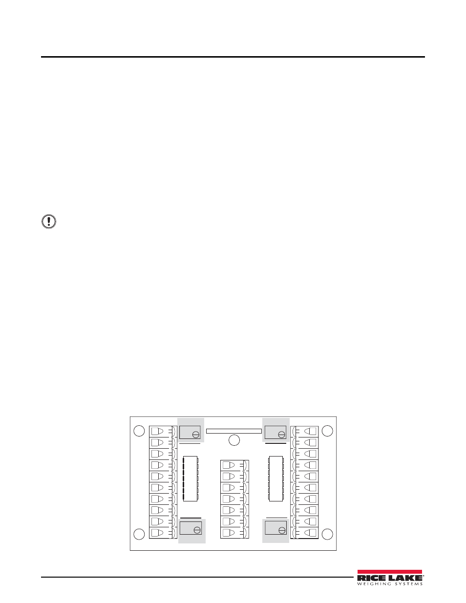
3. Turn all four potentiometers (shaded areas of Figure 3-1) to increase the reading until a clicking sound is
heard from each potentiometer. This ensures the maximum signal from each load cell.
4. Place the test weight over one corner and record the indicated weight.
5. Repeat the process for each of the other three corners. The load cell with the lowest corner reading will be
used as a reference point and will not be trimmed.
CELL 1
CELL 4
CELL 2
CELL 3
INDICATOR
+EX
–EX
+SI
–SI
100 K
+SE
–SE
+EX
+EX
+EX
+EX
–EX
–EX
–EX
–EX
+SI
+SI
+SI
+SI
–SI
–SI
–SI
–SI
SHD
SHD
SHD
SHD
23126
Rev. A
SHD
JU1
JU2
JU3
JU4
100 K
100 K
100 K
Figure 3-1. Trim Potentiometers