0 setup, 1 power connection – Rice Lake DWM-IV Digital Weighmeter Model 5 User Manual
Page 7
3.0 Setup
Set up of the Model 5 requires that the unit be provided with power via the TB1
connector and connected to the load cell via the TB3 connector. The optional connector,
TB2, is used if a serial printer/computer is supplied.
3.1 Power Connection
Refer to the Model 5 circuit board drawing in Section 8.0 BOARD LAYOUT
to locate the power connector TB1, the RS232 connector TB2, and the load cell
connector TB3. Remove the back panel by unscrewing the six screws around the
perimeter. Push the wall transformer cable through the rightmost strain relief,
SR1. Push the load cell cable through the leftmost strain relief, SR3. Using the
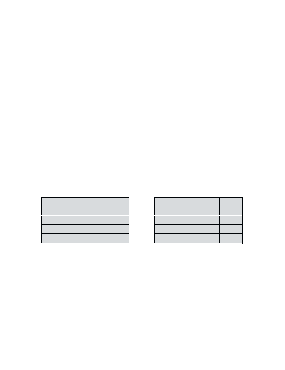
supplied three position terminal block, attach the three conductor power supply
cable wires using a small, flat-blade screwdriver according to the following color
codes:
Wall Transformer
P/N AA-091AG
TB1
Wall Transformer
P/N 48A-9-1000
TB1
BROWN
+IN
RED
+IN
GREEN
GND
WHITE
GND
BLUE
-IN
BLACK
-IN
Ensure that the Green or White wire from the wall transformer is always connected
to the GND terminal as this connection is the safety earth conductor. The unit
becomes grounded or earthed by plugging the wall transformer into a properly
wired three terminal wall receptacle. Never defeat the ground connection in the
interest of safety and noise rejection. Insert the power terminal onto TB1 of the
Model 5 circuit board.
- 1010 Potted & Unpotted Single Point, Aluminum (58 pages)
- 120 Digital Weight Indicator (44 pages)
- 120 Plus Digital Weight Indicator (56 pages)
- 320IS Intrinsically-Safe Digital Weight Indicator - Installation Manual (76 pages)
- 320IS Intrinsically-Safe Digital Weight Indicator - Timer Relay Instruction Sheet (2 pages)
- 320IS Intrinsically-Safe Digital Weight Indicator - Battery Charging Instruction Sheet (2 pages)
- 320IS Intrinsically-Safe Digital Weight Indicator - I/O Module for Intrinsically Safe Systems Installation Manual (15 pages)
- 320IS Intrinsically-Safe Digital Weight Indicator - IS-6V Battery Pack Instruction Sheet (6 pages)
- 320IS Intrinsically-Safe Digital Weight Indicator - IS-EPS-100-240 Power Supply Instructions (6 pages)
- 320IS Plus Intrinsically Safe Digital Weight Indicator - Installation Manual (90 pages)
- 420 Plus HMI Digital Weight Indicator Installation Manual (60 pages)
- 420 Plus HMI Digital Weight Indicator Operator Card (3 pages)
- 420 Plus Digital Weight Indicator - 7.5V DC-to-DC Power Supply Installation (4 pages)
- 420 Plus Digital Weight Indicator - IQ plus 355 - 390-DC - 590-DC & 420 Plus Quick Connector Cable Installation Instructions (1 page)
- 480 Legend Series Digital Weight Indicator Installation Manual (68 pages)
- 480 Legend Series Digital Weight Indicator Operator Card (1 page)
- 480 Panel Mount Option (4 pages)
- 520 Analog Output Card Installation (2 pages)
- 520 Digital Weight Indicator Operator Card (4 pages)
- 520 HMI Digital Weight Indicator Installation Manual (98 pages)
- 520 HMI Digital Weight Indicator Manual - BCD Option (18 pages)
- 520 Configurable Weight Indicator - Remote I/O Indicator Interface Installation and Programming Manual (31 pages)
- 520 Configurable Weight Indicator - ControlNet Interface Installation and Programming Manual (23 pages)
- 520 Configurable Weight Indicator - DeviceNet Interface Installation and Programming Manual (21 pages)
- 520 Configurable Weight Indicator - Ethernet Interface Installation and Configuration Manual (38 pages)
- 520 Configurable Weight Indicator - EtherNet/IP Interfac Installation and Programming Manual (26 pages)
- 520 Configurable Weight Indicator - Profibus DP Interface Installation and Programming Manual (21 pages)
- 550-10-1 Digital Chair Scale - Operation Manual (26 pages)
- 550-10-1 Digital Chair Scale - Technical Manual (34 pages)
- 590-AG Livestock Digital Weight Indicator (56 pages)
- 65059 Mild Steel 3-Module Kit - RL50210 Load Cell Mounting Kit Installation Guide (13 pages)
- 720i Programmable Indicator/Controller - 6V DC-to-DC Power Supply Installation Instructions (4 pages)
- 720i Programmable Indicator/Controller - Installation Manual (122 pages)
- 720i Programmable Indicator/Controller - Operator Card (4 pages)
- 720i Programmable Indicator/Controller - Analog Output Card Installation Instructions (4 pages)
- 720i Programmable Indicator/Controller - CW-90/90X - iQUBE2 - LaserLT WLAN Installation Instructions (12 pages)
- 720i Programmable Indicator/Controller - USB Interface Card Installation Instructions (2 pages)
- 820i Programmable Indicator/Controller - Installation Manual (112 pages)
- 820i Programmable Indicator/Controller - Panel Mount Enclosure Installation Instructions (6 pages)
- 880 Performance Series Indicator/Controller Operators Manual (36 pages)
- 880 Performance Series Indicator/Controller Technical/Service Manual (120 pages)
- 880 Performance Series Panel Mount Indicator/Controller - Adapter Panel Installation (4 pages)
- 880 Performance Series Panel Mount Indicator/Controller - Analog Output Card Option Installation Manual (6 pages)
- 880 Performance Series Panel Mount Indicator/Controller - DeviceNet Interface Option Installation and Programming Manual (28 pages)
- 880 Performance Series Panel Mount Indicator/Controller - EtherNet/IP Interface Option Installation and Programming Manual (32 pages)